


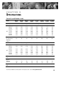
Communication
47
Powerware
®
FERRUPS FE/QFE UPS (500 VA–18 kVA) User’s Guide : Rev A www.powerware.com
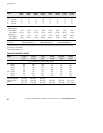
FunctionPasswordShort
Form
Command
systemtest stst None* Starts a system test of the logic, inverter and battery.
time t None Shows the current UPS time. To set the time, enter after
the command.
unshutup u None Turns audible alarm back on.
*If you change parameter 39 to “Yes,” this command requires a User password.
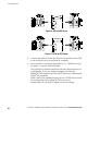
Remote Monitoring
Alarm Signal Contacts: These are relay contacts (rated at 25 Vac/Vdc and
250 mA) that change status on any alarm condition or when the UPS is
turned off. Contacts that close on an alarm are available between Pins 23
and 24. Contacts that open on an alarm are available between Pins 24
and 25.
Inverter On Signal Contacts: These are relay contacts (rated at 25 Vac/Vdc
and 250 mA) that change status when the inverter turns on. Contacts
that close on inverter operation are available between Pins 12 and 13.
Contacts that open on inverter operation are available between Pins 11
and 13.
NOTE FE 500 VA–3.1 kVA models with serial numbers 25000 and greater have
equivalently rated DC solid state switches.
Remote Shutdown
The FERRUPS UPS can be connected to a remote shutdown switch to
shut off output from the UPS to your protected equipment. The
shutdown switch must have a set of contacts that can apply the UPS’s
+12 Vdc on Pin 6 to the UPS’s Pin 21. (You can use Pin 18 instead of
Pin 6;
do not use Pin 14.) Use a shielded, single twisted-pair cable to
connect the switch to the UPS pins. A connection between Pins 6 and 21
(or 18 and 21) shuts down UPS output power to the protected
equipment.
When the UPS Remote Shutdown feature has been activated, the UPS is
in the Off mode and the Emergency Power Off alarm sounds. A control
panel or a terminal connected to the UPS displays “Emergency PwrOff.”