


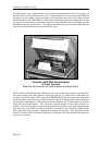
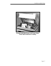

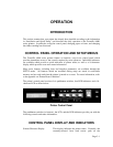

Installation and Quick Setup
Page 2-10
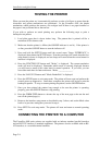
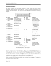
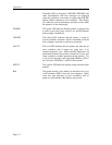
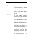
Parallel Interface
The 36-pin connector for the parallel interface is located on the rear of the printer
immediately above the power cord connector. Connect a shielded cable between your
computer and this connector. The pin-out for this connecter is shown in the following
diagram.
Pin Signal Definition Pin Signal Definition
1
19
2
20
3
21
4
22
5
23
6
24
7
25
8
26
9
27
10
28
____________________
DATA STROBE
DATA STROBE
RTN*
DATA 1
DATA 1 RTN*
DATA 2
DATA 2 RTN*
DATA 3
DATA 3 RTN*
DATA 4
DATA 4 RTN*
DATA 5
DATA 5 RTN*
DATA 6
DATA 6 RTN*
DATA 7
DATA 7 RTN*
DATA 8
DATA 8 RTN*
____________
ACKNLG
ACKNLG RTN*
A host generated signal
which signals that data
lines are stable and that
the data may be stored in
the printer buffer.
Host data bit 1 (LSB).
Host data bit 2.
Host data bit 3.
Host data bit 4.
Host data bit 5.
Host data bit 6.
Host data bit 7.
Host data bit 8 (MSB).
A printer generated
signal which is
transmitted after the
receipt of each data
character and negation of
the BUSY.
11
29
12
13
14
16
31
30
32
BUSY
BUSY RTN*
PE
SLCT
±0V
±0V
___________________
INPUT PRIME
INPUT PRIME
RTN*
_________
FAULT
A printer generated
signal which indicates
that the printer is unable
to receive data. Busy
will be set under the
following conditions:
Character received.
Input buffer is full.
Printer is not on line
(see SLCT).
Paper error (see PE).
Fault (see FAULT).
A printer generated
signal which indicates a
paper out or paper
jammed condition.
A printer generated
signal which indicates
that the printer is on line
and ready to receive data.
Signal ground.
Signal ground.
Ignored.
A printer generated
signal which indicates
that the printer requires
attention.
*RTN = Signal ground.
Parallel Interface Connector.
Enter the interface menu as described above. Then press the FUNCTION UP button to
display the “I/O:” function. Now press the VALUE UP button until “Parallel” is displayed
(or CX/TX if that option is installed). Now press the FUNCTION UP button again to display
the “Data Bits:” function. Use the VALUE UP button to select either 7 or 8 data bits as
required by your computer and/or software. This will normally be set to 8.
Finally, press the SETUP button to exit the setup mode and reset the printer. The printer is
now ready to receive parallel data.