4–Hardware Installation
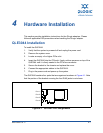
QLE3142 Installation
4-6 NE0154601-00 C
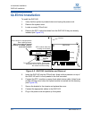
2. Remove the two screws at the top and bottom of the QLE3142 that hold the
bracket in place.
3. Gently pull the bracket away from the QLE3142 until it disconnects from the
optical module housings.
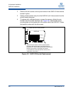
4. To replace with a different bracket, reverse the process, sliding the new
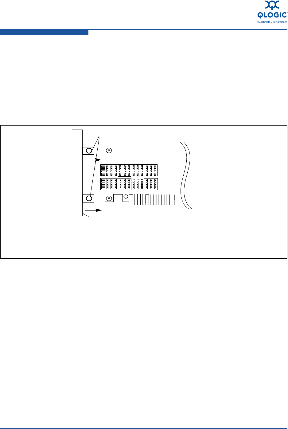
bracket over the module housings (see Figure 4-8). Note that the screw
mounting tabs on the bracket go on the solder side of the QLE3142. Fasten
the bracket in place with the two screws.
Figure 4-8. QLE3142 Bracket Replacement
QLE3142
Housing
Housing
2. Fasten the two mounting screws.
1. Attach the new bracket. The two optical module
cutouts on the bracket slide over the housings on
the QLE3142. The mounting screw tabs on the bracket
should line up with the mounting screw holes
on the QLE3142. Note that the tabs will be on the
solder side of the board.


