Airborne Enterprise Module Databook Quatech, Inc.
100-8080-110 8/11/2009 13
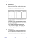
5.1 Digital UART Ports
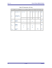
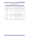
The units supports two digital UART ports, use of these ports is determined by
the device type choice made in firmware. The details of the ports can be seen in
Table 3.
The availability of UART2 for these device types is selected in firmware.
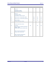
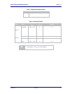
Table 3 - UART Pin Definition
Device Type
UART
Serial
All
Pin Definition
UART1
Pin
UART2
Pin
UART1
Pin
UART2
Pin
Debug
Data out (D
OUT
)
28
21
28
21
6
Data In (D
IN
)
24
9
24
9
8
Clear-to-Send (CTS)
12
19
12
Ready-to-Send (RTS)
18
17
18
Transmit Enable (/TXEN)
17
Receive Enable (/RXEN)
19
Serial Mode (SER_MOD)
22
The primary UART supports a 4-wire interface; the secondary port supports 4-
wire interface except when being used with the Serial Device type, in which case
it is reduced to a 2-wire only.
The primary digital UART can be used as the primary connection for the Serial
device type. This type supports a 7-wire interface to allow the definition of the
serial interface type (RS232/3422/485) and the data transfer direction. Definitions
of this interface can be seen in Table 3.
The UART1 and UART2 interfaces support the following configurations:
BAUD: 300, 600, 1200, 2400, 4800, 9600, 14400, 19200, 28800, 38400,
57600, 115200, 230400, 460800, 921600
Flow Control: None, Hardware (CTS/RTS), Software (XON/XOFF)
Default settings: 9600, 8, N, 1, No Flow Control.
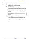
5.2 Ethernet PHY Port
A 10/100 Ethernet PHY interface is supported when the Ethernet device type is
selected in firmware. This interface is a 10/100Mbps interface that supports auto
negotiation and cross-over cabling. The interface also supports both half and full
duplex for 10Mbps and 100Mbps.
The interface uses a Broadcom BCM5241A Ethernet PHY, please refer to the
manufacturers datasheet for interface details and appropriate design guidelines.


