Airborne Enterprise Module Databook Quatech, Inc.
100-8080-110 8/11/2009 23
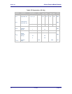
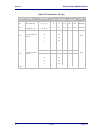
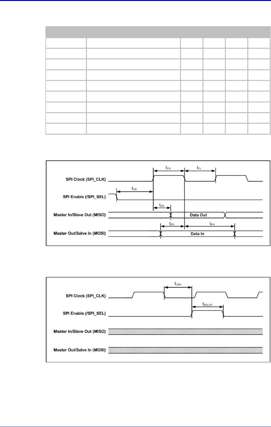
Table 13 - SPI AC Timings
Symbol
Parameter
Min
Typ
Max
Units
f
MAX
Maximum Clock Frequency
8.00
MHz
t
CS
SPI Select Low to Clock Rising Edge
100
ns
t
CH
Clock High
62.5
ns
t
CL
Clock Low
62.5
ns
t
DA
Clock High to Data Out
60
ns
t
DS
Clock Low to Data In Valid Set-up time
14
ns
t
DH
Clock Low to Data Valid Hold time
2
ns
t
CSH
Clock Falling Edge to SPI Select High
100
ns
t
DELAY
SPI Select High to SPI Select Low
40
ns
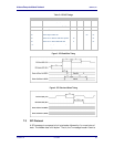
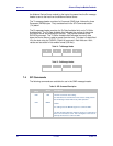
Figure 3 - SPI Read/Write Timing
Figure 4 - SPI Clock and Select Timing
7.3 SPI Protocol
A SPI message is composed of a 4 byte header followed by 0 or more bytes of
data. The header data is full-duplex. That is, the Tx message header is sent to


