


9 COMMUNICATIONS REGISTER
The MPA-200 is equipped with an onboard communications register which gives
the user options pertaining to the clocks and testing. The user can specify the
source and type of clock to be transmitted or received. Test mode bits pertain only
to the DTE versions and can be ignored if using a MPA-200 configured DCE.
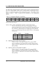
The address of this register is Base+4. Table 14 and the descriptions that follow
detail the communications register.
NOTE:
The Local Loopback Test and the Remote Loopback Test cannot be
performed simultaneously. Thus, bits D5 and D4 of the communications
register should not be simultaneously set (logic 1) .
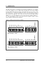
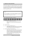
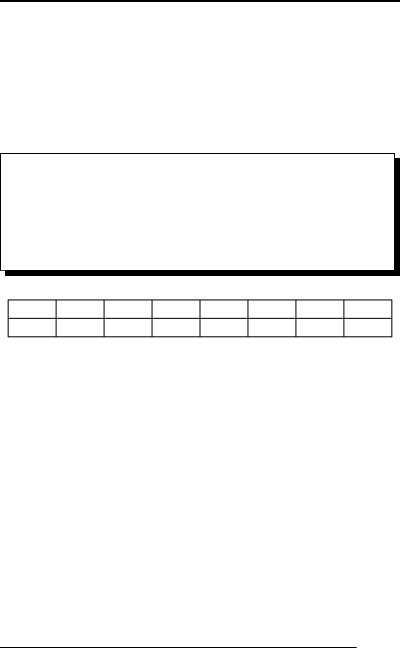
Table 14 COMMUNICATIONS Register - Read/Write
TXDENRXDENTCKENRCKENRLENLLEN0TM ST
D0D1D2D3D4D5D6D7
D7 -TEST MODE STATUS (DTE only, read only):
This bit can read the status of the Test Mode signal on a DTE,
allowing the user to monitor this signal without generating any
interrupts.
D6 - Reserved, always 0.
D5 -LOCAL LOOPBACK ENABLE (DTE only):
When set (logic 1), this bit allows the DTE to test the functioning
of the DTE/DCE interface and the transmit and receive sections of
the local DCE. When cleared (logic 0), no testing occurs.
D4 -REMOTE LOOPBACK ENABLE (DTE only):
When set (logic 1), this bit allows the DTE to test the transmission
path up to and through the remote DCE to the DTE interface and
the similar return transmission path. When cleared (logic 0), no
testing occurs. If jumper J8 is in place the Remote Loopback is
also used to control the Sync input of the Channel A data receiver.
This is useful in situations where it is desired to receive
unformatted serial data.
23 Quatech Inc., MPA-200/300 Manual