


10.1 DTE Configuration
The control signals that the DTE can generate are the Request To Send (RTS) and
Data Terminal Ready (DTR). It can receive the signals Carrier Detect (CD), Clear
to Send (CTS), and Data Set Ready (DSR). All of the control signals are
controlled through channel A of the SCC, with the exception of the DSR signal,
which is received on channel B.
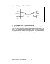
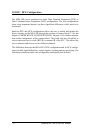
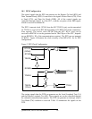
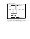
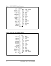
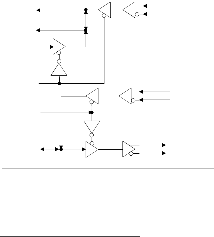
The DTE’s transmit clock (TCLK from the SCC TRXCA pin) can be transmitted
on TTCLK or received on RTCLK depending on TCKEN (D2 of the communica-
tions register). The receive clock (RCLK from the SCC RTxC pins) can be
received on RRCLK or can be generated on the TRxCB pin of the SCC, depend-
ing on RCKEN ( D3 of the communications register). The DTE can not transmit
its RCLK. Figure 4 illustrates the clock circuitry of the MPA-200 for it's DTE
configuration.
Figure 2 DTE Clock Configuration
TRXCA
RTXCA
RTXCB
RRCLK
RTCLK
TRXCB
RCKEN
TTCLK
TCKEN
(RCLK)
(TCLK)
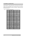
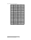
The testing signals that the DTE can generate are the Local Loopback Test (LL)
and the Remote Loopback Test (RL). These signals are can be controlled through
the onboard communications register. The DTE can generate an interrupt when a
Test Mode (TM) condition is received. Table 15 summarizes the signals on the
DTE.
Quatech Inc., MPA-200/300 Manual 26