2.4 DTE/DCE Selection
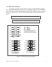
To simplify connections to other devices, each port on the DSC-100 is equipped
with a jumper block that allows the port to be configured as either a DTE- or DCE-type
device. This allows the DSC-100 to connect to either DTE- or DCE-type devices without
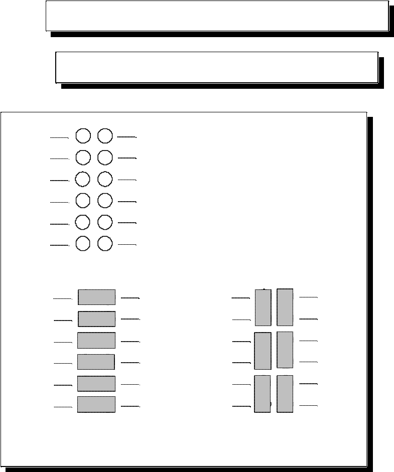
using a null modem cable. The DTE/DCE selection jumper blocks are illustrated in
Figure 5.
J2 is used for serial port 1, closest to the bottom of the board.
J1 is used for serial port 2, closest to the top of the board.
1
6
5
4
8
7
2
3 9
10
11
12
pin 3
RxD
pin 7
CTS
pin 4
DSR
TxD
pin 2
RTS
pin 8
DTR
pin 6
J2 -- Port 1
J1 -- Port 2
These jumper blocks are used to
connect RS-232 signals to the
various pins of the D-9 connectors.
1
6
5
4
8
7
2
3 9
10
11
12
pin 3
RxD
pin 7
CTS
pin 4
DSR
TxD
pin 2
RTS
pin 8
DTR
pin 6
1
6
5
4
8
7
2
3 9
10
11
12
pin 3
RxD
pin 7
CTS
pin 4
DSR
TxD
pin 2
RTS
pin 8
DTR
pin 6
DTE configuration
(factory default)
DCE configuration
Figure 5 --- DTE or DCE output selection
Quatech DSC-100 User's Manual
8


