


3 Hardware Installation
1. Turn off the power of the computer system in which the DSCLP-200/300 is to
be installed.
2. Remove the system cover according to the instructions provided by the
computer manufacturer.
3. Make any desired optional jumper setting changes.
4. Install the DSCLP-200/300 in any empty PCI expansion slot. The board
should be secured by installing the Option Retaining Bracket (ORB) screw.
5. Replace the system cover according to the instructions provided by the
computer manufacturer.
6. Attach and secure the cable connectors to the desired equipment.
7. Turn on the power of the computer system.
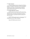
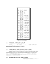
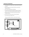
The output of the DSCLP-200/300 is two female 9-pin D-connectors.
J2
J4
J5
SPAD
X4
X2
Clock multiplier/
scratchpad select
Termination select
Interface configuration
J1
J2
J3
J4
J5
J6
J7
J8
port 1
port 2
Serial
Port
2
Serial
Port
1
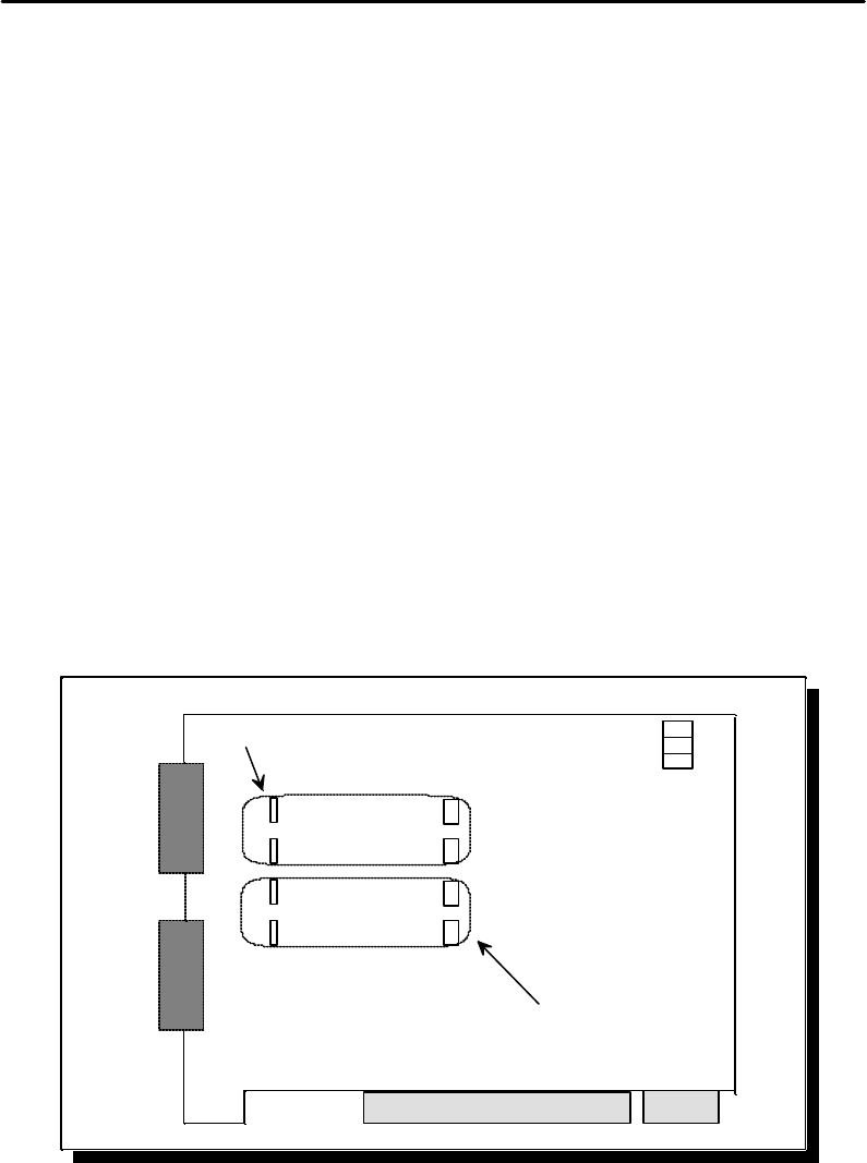
Figure 6 --- Jumper/connector locations
8 DSCLP/SSCLP-200/300 User's Manual