


ASM-10/8 Installation and Operation Manual Chapter 1. Introduction
09/10/00 16:26 Overview 1-3
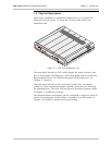
ASM-10/8
RCV CLK
V.54 DLY-OFF
EXT CLK
V.54 DLY-ON
EXT CLK
V.54 DLY-ON
RCV CLK
V.54 DLY-OFF
ASM-10/8
ASM-10/8 ASM-10/8
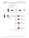
Digital
Service
Network
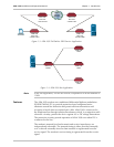
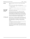
Figure 1-3 ASM-10/8 Tail-End for DDS Service Application
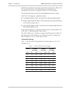
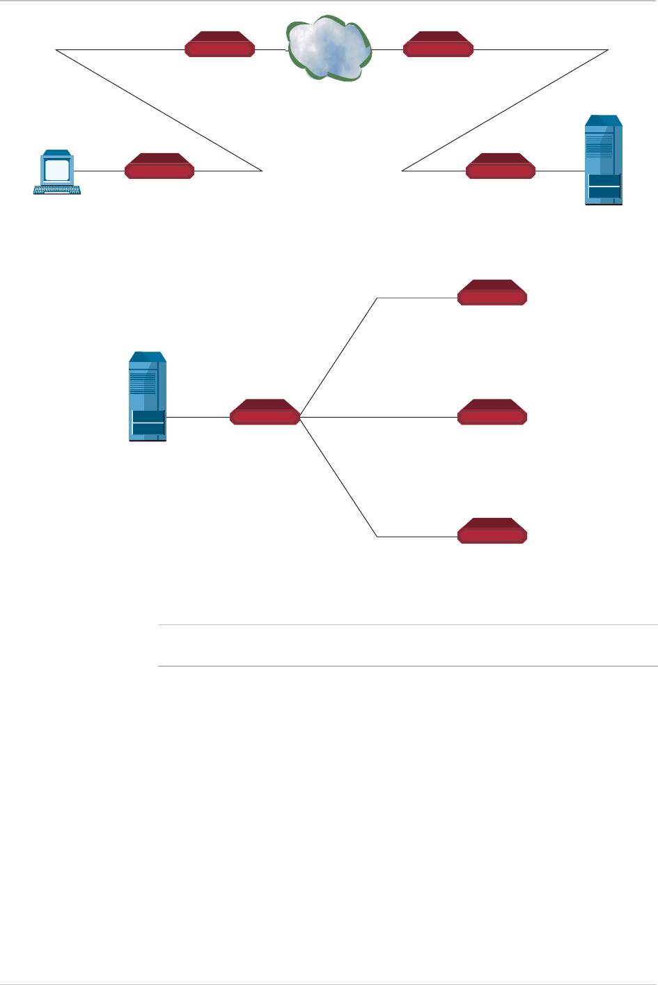
ASM-10/8
Master
ASM-10/8
Slave
ASM-10/8
Slave
ASM-10/8
Slave
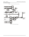
Figure 1-4 ASM-10/8 Star Application
Note
In the star application, set the XMT and RCV impedance of all the modems to
150W.
Features
The ASM-10/8 modem uses conditioned differential diphase modulation
(EUROCOM Std. D1) to provide protection from background noise,
eliminate normal line distortion and permit efficient transmission and
reception of serial data over twisted pair cable. ASM-10/8 is connected to
the telephone line through isolation transformers which, in conjunction with
electronic circuitry, protect the device against AC or DC voltage fluctuations.
The protection circuitry permits operation of ASM-10/8 even when DC is
connected to the line.
The modem's transmit level and transmit and receive impedances are
independently selectable. The transmit timing is either provided internally,
or it is derived externally from the data terminal or regenerated from the
receive signal. The modem's receive timing is regenerated from the receive
signal.