


Chapter 2. Installation and Setup ASM-10/8
Installation and Operation Manual
2-4 Installation and Setup 09/10/00 16:26
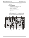
Table 2-1 ASM-10/8 Internal Jumpers and Switches
Item Jumper Description Values Default Setting
1 SWITCH Enables activation of DIG, ANA and
REM loopbacks via the front-panel
push buttons
EN – The loopbacks can be
activated via the front panel
DIS
– The loopbacks cannot
be activated via the front
panel
EN
2 2W/4W Selects 4-wire or 2-wire operation 4W – 4-wire operation
2W – 2-wire operation
4W
Note: When using 2-wire operation, connect both wires to the XMT screws of the terminal.
3 AGC Controls the AGC operation.
Refer to Configuration Considerations
below for detailed explanation of the
AGC settings.
ON – AGC is always active
CTRL
– ACG is active only
when DCD turns on
ON
Note: When set to CTRL, ACG remains at its last level of amplification if DCD goes off.
4 CARRIER Selects the transmit carrier mode. ON – Transmit carrier is
constantly On
CTRL
– Transmit carrier is
On only if RTS is high
ON
Note: Set CARRIER to CTRL when using ASM-10/8 in multipoint applications.
5 XMT LEVEL Selects the transmit output level to the
line
0 dbm
-3 dbm
-6 dbm
-9 dbm
0 dbm
6 XMT IMPD Selects transmit line impedance 600
300
150
LOW
150
Note: Set XMT IMPD to LOW when using ASM-10/8 in multipoint applications.
7 RPF Enables the Remote Power Failure
notification (ASM-10/8/R only)
ON
– RPF notification
enabled
OFF
– RPF notification
disabled
ON
Note: Set RPF to OFF when using ASM-10/8 in multipoint applications.
8 PIN 18 Controls the local analog loopback
activation via the DTE pin 18
EN
– The analog loopback
activation from the DTE
enabled
DIS
– The analog loopback
activation from the DTE
disabled
EN