


Package Contents 2-1
Chapter 2
Installation and Setup
2.1 Introduction
This chapter provides instructions for mechanical and electrical installation of the
ASM-20 standalone model.
• For rack installation of the ASM-20, see Chapter 5, Card Cage Version.
• For ETH interface installation see Appendix A, Ethernet Interface.
• For G.703 interface installation, see Appendix B, IR-G.703 Codirectional
Interface (64 kbps).
• For X.21B interface installation, see Appendix C, IR-X.21B Interface Module.
• For V.36 interface installation, see Appendix E, Connection to RS-422.
After installation has been completed, see Chapter 3, Operation for operating
information and system checkout to assure normal operation.
2.2 Site Preparation and Prerequisites
Install ASM-20 within 1.5m (5 ft) of a grounded, easily accessible AC outlet. The
outlet should be capable of furnishing 115 VAC or 230 VAC (depending on rated
voltage of unit).
For DC units, the DC supply must be adequately isolated from the mains supply.
To prevent a fire hazard, the line supply lead should be fused or current limited.
Allow at least 90 cm (36 in) of frontal clearance for operating and maintenance
accessibility. Ensure that there is at least 10 cm (4 in) clearance at the rear of the
unit for signal lines and interface cables.
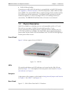
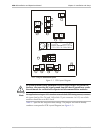
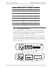
2.3 Package Contents
The ASM-20 package includes the following items:
• ASM-20
• AC cord
• 48 VDC plug (optional)
• Adapter cable for the different interfaces (optional)
• ASM-20 Installation and Operation Manual.