


Chapter 2 Installation and Setup ASM-20 Installation and Operation Manual
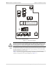
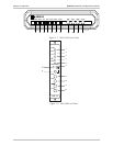
2-4 Setting Internal Jumpers and Switches
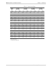
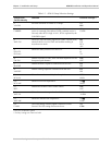
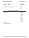
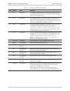
Table 2-1. ASM-20 Strap Selection Settings
Jumper and
Switch Identity
Function Possible Settings**
J1
V54 DIS
Prevents activation of remote V.54 loops. EN
DIS
J2
CARRIER
Selects the transmit carrier mode. When ON, transmit
carrier is constantly ON. When CNTRL, transmit carrier is
ON only when RTS is High. In X.21, RTS is replaced by the
CONTROL signal.
ON
CNTRL
J3
XMT CLK
Selects the transmit timing signal from either: internal clock,
external clock or receive clock and enables working in
Asynchronous mode.
INT
EXT
RCV
ASY
J4
RTS-CTS
DLY (ms)
Selects the delay between RTS and CTS. 0
9
70
J6
SW. EN.
Enables activation of DIG, ANA and REM loopbacks via the
front panel push buttons.
ON
OFF
J7
RLB DTE
Enables Remote Loopback command from the DTE.
EN
DIS
J8
ALB DTE
Enables Analog Loopback command from the DTE.
EN
DIS
J9
RCV LVL
Selects the receiver sensitivity level required.
LOW
HIGH
J10
RCV IMP
Selects receive line impedance.
150Ω
HIGH
J11
RPF*
Enables the Remote Power Failure feature.
ON
OFF
J12
XMT LVL
Selects the transmit output level to the line.
0 dBm
-6 dBm
J13
XMT IMP
Selects the transmit line impedance.
150Ω
LOW
J14
CHASS
The CON setting connects Signal Ground to Chassis
Ground. The DIS setting disconnects them.
DIS
CON
* Only for standalone option
** Factory settings are shown in bold.