


Appendix A Ethernet Interface ASM-20 Installation and Operation Manual
A-2 IR-ETH Connector Options
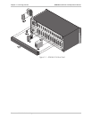
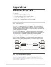
Line Connector
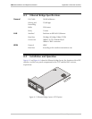
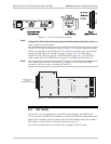
Figure A-2 ASM-20 Rear Panel with IR-ETH/UTP Connector Option
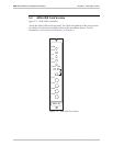
Line Connector
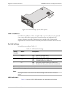
Figure A-3 ASM-20 Rear Panel with IR-ETH/BNC Connector Option
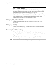
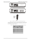
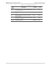
DB-25
(13) RCV(+)
(12) RCV(-)
(11) XMT(+)
(9) XMT(-)
(7) GND
7
9
13
11
12
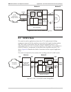
Figure A-4 IR-ETH Connector for the ASM-20 Rack-Mount Version
When using the RJ-45 connector, the customer must prepare a mechanical cable
for adapting the DB-25 pinout to that of RJ-45. The pinouts of the DB-25 and
RJ-45 connectors are given in Table A-1.
Table A-1 DB-25 and RJ-45 Pin Assignment for IR-ETH Connection
Signal Pin
DB-25 RJ-45
RCV (+) 13 3
RCV (-) 12 6
XMT (+) 11 1
XMT (-) 9 2
GND 7 -