TCCI-1 • 5
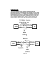
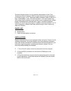
The block diagram shown is a very general interpretation of the J-Com
Transceiver control Computer. When a signal is sent from your computer it
is in binary (a logic 1 or 0). The binary signal is between 3 and 25 volts for a
logic 1 and between -3 and -25 volts for a logic 0. Your radio doesn’t use
such voltage levels, therefore a level shifter is used to change these voltage
levels to something that it can deal with. A logic 1 is shifted to become
between 3.2 and 5 volts and a logic 0 is shifted to become between 0 to 2.4
volts. A Kenwood i different than other radios though,in that it require the
data to be inverted.
PARTS LIST
❒ Software Disk
❒ Cable with appropriate connectors
INSTALLATION:
Please understand that you must possess a basic computer “literacy” for the
following instructions. If you have trouble, your local computer or amateur
radio club can be quite helpful in explaining terms and the intricacies of your
individual computing system, including any software “glitches” that you
encounter while installing this interface.
❒ 1. Turn off the AC power to both the transceiver and the computer.
❒ 2. Plug the DB-25 connector into the desired COMM port of the
computer.
❒ 3. Plug the transceiver connector into the appropriate jack on the back
of your transceiver. Consult the transceiver manuals if you are unsure
which is the correct jack.


