


8 M1500 Marine Monitor
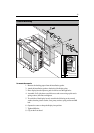
Planning
Before you install your display, plan the installation considering:
• Power requirements
• Cable runs
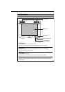
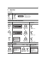
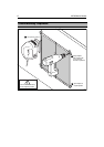
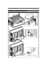
• Display location and mounting options.
• Optional Audio/Video Junction Box location
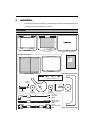
• Additional ancillary parts e.g. keyboard or extra speakers.
Power Requirements
This display is designed to run on ships’ DC power systems rated at 12 V or 24 V.
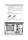
A 2.5m length cable is supplied for connecting the display to the ship’s DC power
system. The DC system should be either:
• Negative grounded, with the negative battery terminal connected to the ship’s
ground.
• Floating, with neither battery terminal connected to the ship’s ground.
CAUTION:
This display is not intended for use on “positive” ground vessels.
The power input cable Earth screen connections must be connected directly
to the ship’s ground.
Grounding the display
It is important that an effective RF ground is connected to the display. You must
ground the display by connecting the drain wire (screen) of the power input cable
to the nearest ground point of the ship’s RF ground system.
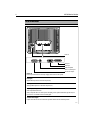
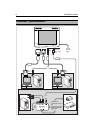
Power Connections
The power connection to the display should be made at either the output of the
battery isolator switch, or at a DC power distribution panel. Raymarine
recommends that power is fed directly to the display via its own dedicated cable
system and MUST be protected by a thermal circuit breaker or fuse, fitted close to
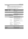
the power connection. Refer to the table below for isolator switch, circuit breaker
or fuse value ratings. Check all terminal connections are clean.
CAUTION:
If you do not have a thermal circuit breaker or fuse in your power circuit, e.g.
fitted to the DC distribution panel, you MUST fit an in-line breaker or fuse to
the positive (red) lead of the power cable.
Vessels Supply Isolator Switch
Min. Rating
Thermal Breaker
Rating
Fuse Value
12 V 15 A 8 A 12 A
24 V8 A4 A6 A