


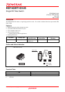

HD74CBT1G125
Rev.1.00 Apr 07, 2006 page 2 of 6
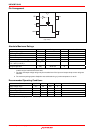
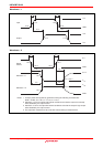
Pin Arrangement
(Top view)
5
4
V
CC
1
2
3
OE
A
GND
B
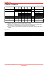
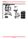
Absolute Maximum Ratings
Item Symbol Ratings Unit Conditions
Supply voltage range V
CC
−0.5 to 7.0 V
Input voltage range
*1
V
I
−0.5 to 7.0 V
Input clamp current I
IK
−50 mA V
I
< 0
Continuous output current I
O
128 mA V
O
= 0 to V
CC
Continuous current through V
CC
or GND I
CC
or I
GND
±100 mA
Maximum power dissipation
at Ta = 25°C (in still air)
*2
P
T
200 mW
Storage temperature Tstg −65 to 150 °C
Notes: The absolute maximum ratings are values which must not individually be exceeded, and furthermore, no two
of which may be realized at the same time.
1. The input and output voltage ratings may be exceeded even if the input and output clamp-current ratings are
observed.
2. The maximum package power dissipation was calculated using a junction temperature of 150°C.
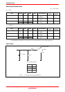
Recommended Operating Conditions
Item Symbol Min Max Unit Conditions
Supply voltage range V
CC
4.0 5.5 V
Input voltage range V
I
0 5.5 V
Output voltage range V
I/O
0 5.5 V
Input transition rise or fall rate ∆t / ∆v 0 5 ns / V V
CC
= 4.5 to 5.5 V
Operating free-air temperature Ta −40 85 °C
Note: Unused or floating inputs must be held high or low.