14
3.2.2
What is the difference between Boot Mode and User Mode?
The Renesas Flash devices have different modes of operation which are controlled by the state of the mode
pins when the device is brought out of reset. Most devices have an asynchronous serial Boot Mode and a
User/User Program Mode.
Generally, (asynchronous serial) Boot Mode connections, start with an autobaud – sending synchronisation
data packets to setup initial communications at a given baud rate. Additionally, for most devices, the entire
flash will be erased as part of the connection process, thus preventing any Intellectual Property held on the
device from being read from Boot Mode.
For a User Mode connection, the device must already be programmed with some code which talks to FDT
and allows programming. Most kernels are supplied with a User Mode micro kernel and test program
(*usually called “uGenU.mot” and “xxxxtest.mot”). These files provide a demonstration of User
Mode programming and must be programmed into the device and be executing before FDT tries to connect
in User Mode. User Mode does not normally force an erase of the flash during the connection process and
does not autobaud to setup initial communications. The demonstration User Mode test programs have the
required Bit Rate Register value compiled into them for setting up initial communications at 9600 baud;
hence User Mode kernels need to be rebuilt for different clock frequencies.
* Note that where the files are to be used as part of an embedded monitor, the User Mode kernel
files may be also output as binary files (.cde) without the reset vector populated. Some kernels
use only a single file for the User Mode test program (e.g. Protocol C kernels).
3.2.3
What is the difference between User Mode and User Program Mode?
Some devices use an additional mode pin to protect the flash from being written or erased by mistake; this
pin is normally known as the “Flash Write Enable” pin (FWE) if it has to be logic high to allow
programming, or the “Flash Write Protect” pin (FWP) if it has to be logic low to allow programming. For
these devices, this pin distinguishes “User Mode” from “User Program Mode”. An FDT User Mode
connection expects the device to be in User Program Mode at the point of programming and erasing, and if
using the FDM, can reset the device into User Mode to execute the programmed code on disconnection.
3.2.4
What are “Protocol A”, “Protocol B”, “Protocol C” and “Protocol D” Kernels?
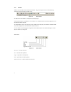
“Protocol A” - For some 0.8μm, 0.6μm and 0.35μm flash devices using FDT 1.5 style kernels.
These are legacy kernels that are not supported and not included in the FDT installer. Protocol A kernels
are not available in the Japanese versions of FDT. Protocol A kernels support use of the UPB but not the
FDM. The kernel needs to be rebuilt for different crystal frequencies in Boot and User Modes, and for
changing the PMODE pin if using the UPB. Please refer to the documentation supplied with the kernels for
additional information.
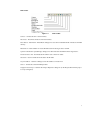
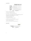
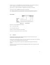
“Protocol B” – For 0.35μm devices. These support the FDM but not the UPB.
Boot Mode - The kernel (made up of the Boot Mode Micro Kernel, Boot Mode Main Kernel, and the Write
and Erase modules) is held on the PC and downloaded as required. The Boot Mode kernel does not need to
be rebuilt for different crystal frequencies; this information is stored in the FDT project and downloaded at
runtime and initial communication is achieved by the autobaud (where FDT sends 0x00 data until the
device synchronises with it).


