


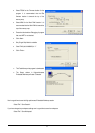
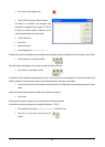

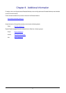

• Right click on the FlashLEDs(); function and
select ‘Go to cursor’.
The code will execute to the selected line and stop. An automatic breakpoint was inserted in the code and then removed after calling the
break.
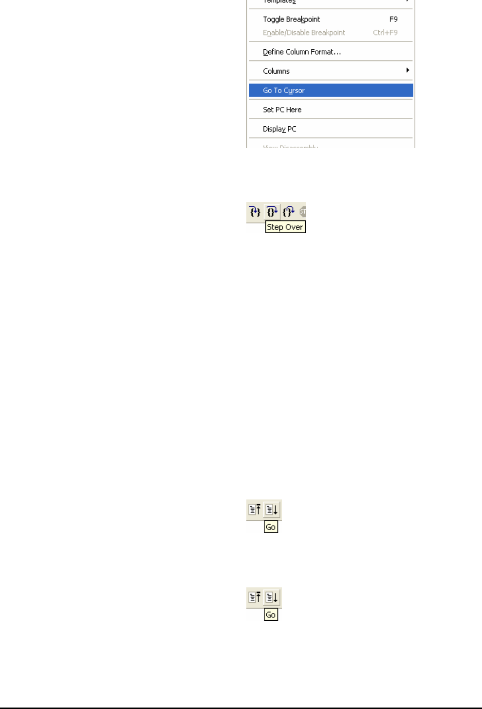
• Press ‘Step Over’ on the Debug Tool Bar.
The code will run and flash the LEDs 200 times. The debugger will not exit until all 200 flashes have completed or a button is pressed on the
board
• To stop the LEDs flashing press the SW1 button on the board to exit the FlashLEDs() function.
The code will run to the breakpoint we previously set on the TimerADC function, note that the yellow PC arrow will now be superimposed
on the breakpoint indicator, this conforms the breakpoint has been reached.
The TimerADC function initialises an interrupt on an available internal timer. On a compare match in the timer module an interrupt is
generated. In the TimerADC code the interrupt reads the last ADC conversion from the external potentiometer and uses the result to set the
next compare match value. The ADC conversion is then re-started.
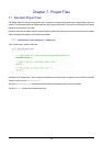
The interrupt initialisation is completed as part of the hardware setup. This is contained in the file ‘interrupts.c’.
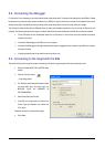
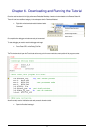
• Open the file ‘interrupts.c’ by double clicking on the file in the Workspace window.
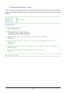
• Review this file and find the interrupt function that changes the LED pins; TimerA0Handler(void).
• Set a breakpoint on the line where the LED pins are modified.
• Press <Go> or <F5> to run the code from the current
PC position.
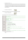
The code will stop in the interrupt routine. It is now possible to step through the interrupt function.
• Remove the breakpoint in the interrupt by double clicking again before exiting the function.
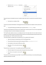
• Press <Go>to run the code from the current PC
position.
The code will now run to the infinite loop at the end of Main. The user LEDs should now be flashing. You can modify the flashing rate by
adjusting the potentiometer on the board.
11