


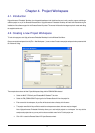
5.2. Connecting the debugger
For this tutorial it is not necessary to provide an external power supply to the board. The power will be obtained from the USB port. Please
be aware that if you have too many devices connected to your USB port it may be shut down by windows. If this happens remove some
devices and try again. Alternatively provide an external power source taking care to ensure the correct polarity and voltage.
The Quick Start Guide provided with the Renesas Starter Kit board gives detailed instructions on how to connect the E8a to the host
computer. The following assumes that the steps in the Quick Start Guide have been followed and the E8a drivers have been installed.
• Fit the LCD module to J8 on the Renesas Starter Kit, so it lies above J1. Insure all the pins of the connector are correctly
inserted in the socket.
• Connect the E8a debugger to the USB port on your computer.
• Connect the E8a Debugger to the target hardware ensuring that it is plugged into the connector marked E8 which is nearest
the power connector.
• If supplying external power to the board this can be turned on now.
5.3. Connecting to the target with the E8a
This section will take you through the process of connecting to the device, programming the Flash and executing the code.
• Select the ‘SessionM16C_E8a_SYSTEM’ debug
session.
• Click the <Connect> button
on the debug toolbar
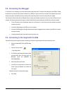
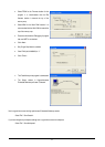
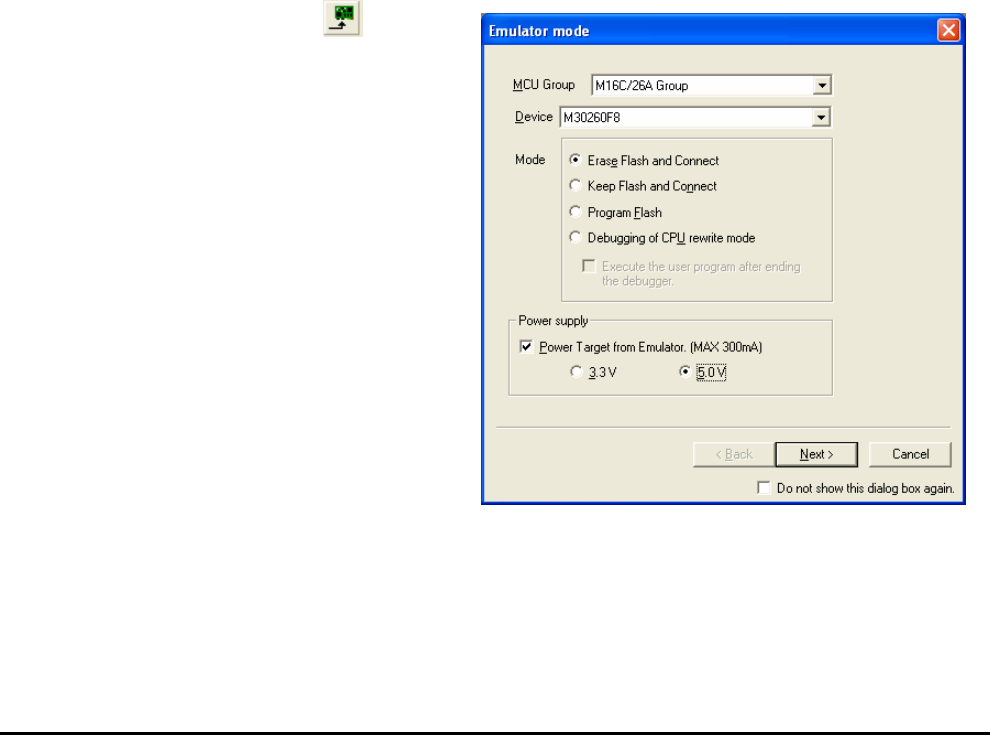
• The ‘Emulator mode’ dialog will be shown. Select
the correct MCU group and device type (e.g.
M16C/26A Group and M30260F8 for
E8A_RSKM16C26A).
• Select ‘Erase Flash and Connect’.
• If the E8a is to provide power to the board, set
‘Power Target from Emulator’ and choose the
‘5.0V’ option.
Otherwise connect a 5V centre positive supply.
• Click <Next>.
7