


M306NKT-EPB User’s Manual 2. Setup
REJ10J0519-0200 Rev.2.00 Oct. 16, 2006 Page 36 of 104
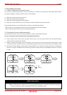
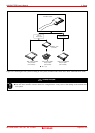
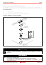
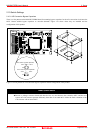
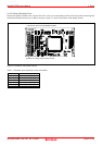
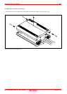
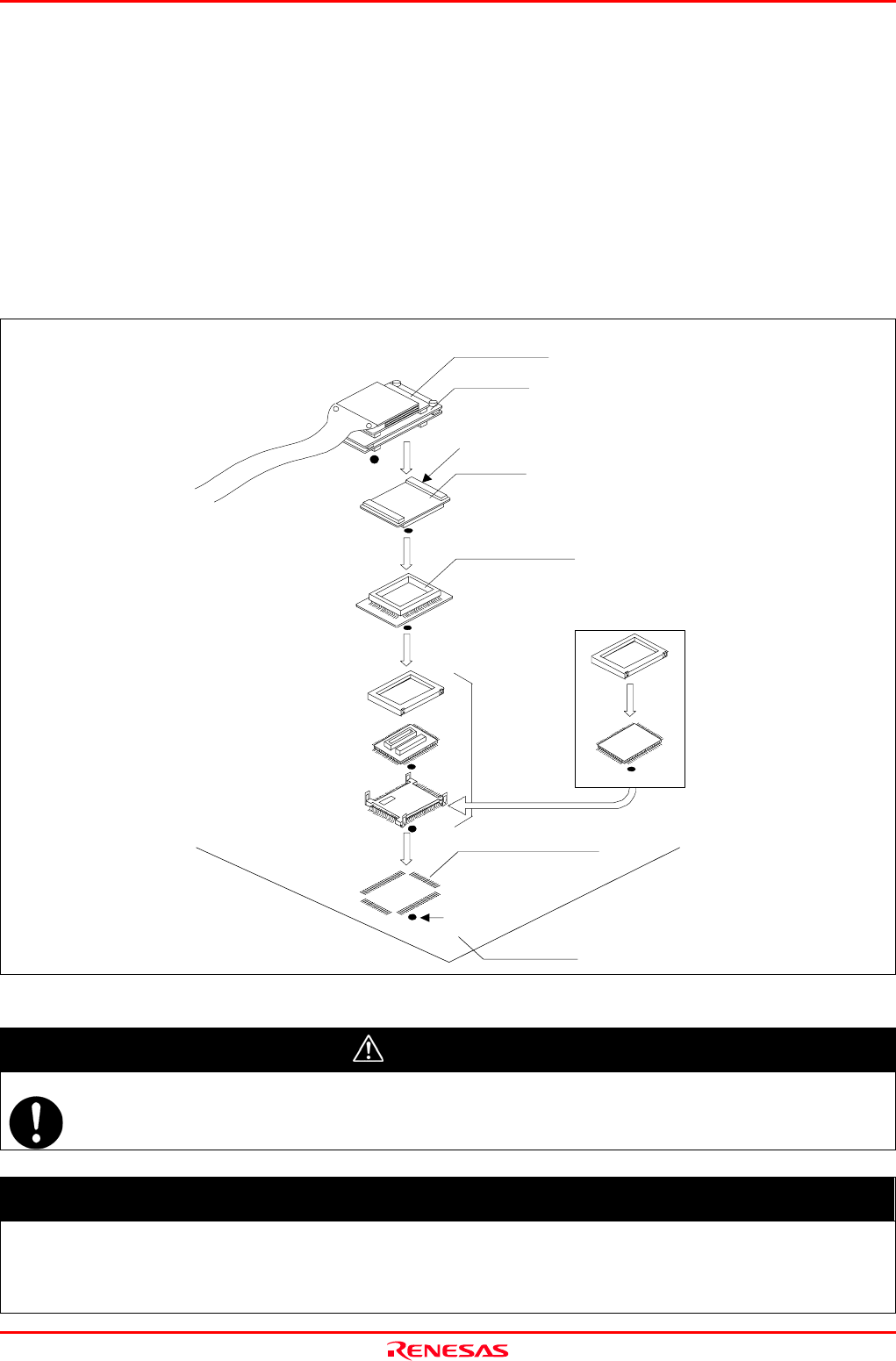
2.9.4 Connecting to a 100-pin 0.65mm Pitch Foot Pattern (Part 3)
Here following is a procedure of connecting to a 100-pin 0.65mm pitch foot pattern on the user system using the M3T-
DUMMY100S (not included). For details on the M3T-100LCC-DMS (not included) and M3T-DUMMY100S (not included),
refer to each user's manual.
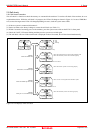
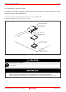
(1) Attach the M3T-DUMMY100S to the user system.
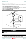
(2) Attach the M3T-100LCC-DMS to the M3T-DUMMY100S.
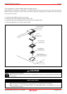
(3) Attach the CN2 side of the M30800T-PTC to the J4 side of the M306NKT-EPB.
(4) Attach the M30800T-PTC to the M3T-100LCC-DMS.
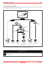
M3T-100LCC-DMS
(not included)
CN2 side
(3)
(4)
M30800T-PTC
(2)
FLASH MCU, etc
On-board evaluation
M3T-DUMMY100S
(not included)
(1)
100-pin 0.65mm pitch
No. 1 pin
User system
M3T-FLX160-EPB
M306NKT-EPB
(PRQP0100JB-A) foot pattern
Figure 2.12 Connecting to a 100-pin 0.65mm pitch foot pattern (Part 3)
CAUTION
Note on Connecting the User System:
z Take care not to attach a converter board in a wrong direction. It may cause a fatal damage to the emulator and
user system.
IMPORTANT
Notes on Connectors of the Converter board:
z The connectors of the M30800T-PTC are guaranteed for only 50 insertion/removal iterations.
z The connectors of the M3T-100LCC-DMS and M3T-DUMMY100S are guaranteed for only 20
insertion/removal iterations.