(3/8)
4. Setting Up
This chapter describes how to set up the M38C29T-ADF.
(1) Mount the emulator MCU on the M38C29T-ADF.
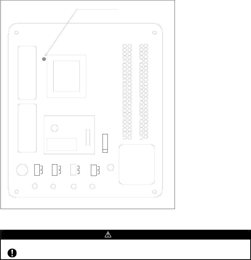
After checking the position of the No. 1 pin of the emulator MCU, mount the emulator MCU referencing Figure 4.1.
(2) Insert the connector on the tip of the emulator probe to the socket on the emulator MCU.
For the M38000T2-CPE, the converter board PCA4933 is required between the emulator probe and emulator MCU.
Figure 4.1 Position of No. 1 pin of the M38C29T-ADF's emulator MCU
CAUTION
Cautions to Be Taken for This Product:
Always shut OFF power before connecting this product. The power ON state could destroy internal circuit.
J3
OSC - 2
1
5
10
15
20
25
100
26
7650
80
85
90
95
45
30
35
40
51
55
60
65
70
75
J1
J2
M38C2 9T - ADF
MADE I N J APAN
IC1
1
30
31
50
51
80
81
100
32K
OSC
RE SE T
SW5
SW1
PORT/XCIN
XC I N
PO
RT
SW2
VRE F
Vc
c
J1-21
TP1
Vc c
TP4
VREF
TP3
RESET
TP2
Vs s
C6
IC3
1
Universal part
Universal part
SW3
CNVs s
Vc c
Vs s
No. 1 pin
SW4
XOUT
Vcc
NC


