(4/8)
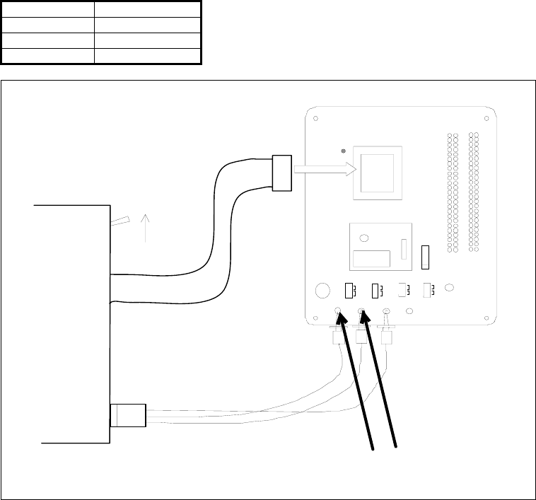
(3) Connect the RESET cable (white) and the GND cable (black) of the emulation pod to the RESET (TP3) pin and Vss (TP2) pin of
the M38C29T-ADF respectively. And connect the Vcc cable (red) to the Vcc (TP1) pin.
(4) Set the MCU type select switch of the M38000T2-CPE to the RLSS side.
(5) Connect a power supply (not included) to the Vcc (TP1) pin of the M38C29T-ADF. And connect the GND output of the power
supply to the Vss (TP2) pin. Use the power supply whose rising time is 10ms or less.
Table 4.1 lists the correspondence of the connector cables and signals, and Figure 4.2 shows the connection pattern.
Table 4.1 Connector cables of the M38000T2-CPE and applicable signals
Cable color Signal
WHITE RESET
BLACK Vss
RED Vcc (SENSE)
J3
OSC-2
M
3
8C29T- ADF
REV. B
IC1
1
30
31
50
51
80
81
100
C1
RES ET
SW5SW1
PORT/ XC
IN
XCIN
PORT
SW2
VRE F
Vcc
J1 - 21
C6
IC3
1
C5
SW3
CNVs s
Vc
c
Vs s
WH IT E
RED
BLACK
Emulator
+5V 0V
SW4
CNVs s
VccNC
RLSS/RLFS
TP1 TP2 TP3 TP4
J1 J2
Figure 4.2 Connection pattern of the M38C29T-ADF


