


(2/9)
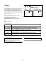
1. Outline
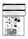
The R0E330850ACBP0 is a protection board for the M16C/60
Series M16C/62P Group and M32C/80 Series emulator. This
product protects the emulator from improper connections by
connecting to between the converter board and emulator.
This product is designed to protect the emulator from troubles
caused by applying overvoltage to port pins. Note that it cannot
protect the emulator when applying overvoltage or reverse
voltage to the power pins, or applying more voltage than the
allowable voltage to each pin.
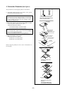
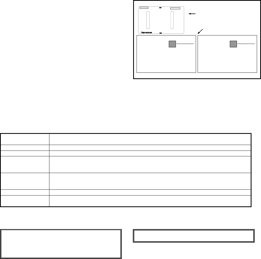
2. Package Components (See Figure 1)
(1) R0E330850ACBP0 protection board ......................... 1pc.
(2) R0E330850ACBP0 User's Manual (This manual) ..... 1pc.
(2) R0E330850ACBP0 User's Manual (Japanese)........... 1pc.
R0E330850ACBP0
ユーザーズマニュアル
RENESAS
ルネサステクノロジ
www.renesas.com
(1/*)
R0E330850ACBP0
User's Manual
RENESAS
Renesas Technology
www.renesas.co m
(1/*)
R0E330850ACBP0
protection board
R0E330850ACBP0
User's Manual (Jpn/Eng)
TOOL SIDE
R0E330850ACBP0 REV.A
MADE IN JAPAN
Pb Free
40
b
40
a
1a1b
J2
J1
40a
1a
40b
1b
LED1
LED2
Figure 1 Package components of the R0E330850ACBP0
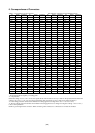
3. Specifications
Table 1 Specifications
Applicable products
M30830T-EPB, M30850T2-EPB, M30870T-EPB, M30880T-EPB, M3062PT2-EPB,
M30850T3-CPE, M30870T2-CPE, M3062PT3-CPE
Interface connectors 80pin 0.8mm pitch (Matsushita Electric Works, Ltd.)
Vcc 3.0 - 5.5 V (When the power pin Vcc1 is set to 5.6 V or more, LED1 and LED2 light.)
Protect function
Overvoltage: When applying voltage up to +10 V, the input voltage is limited by a diode.
Reverse voltage: When applying voltage up to -10 V, the input voltage is limited by a diode.
Over current: When the signal is short-circuited, the current is limited.
Protected pins*
Signal input/output pins except pins below.
Pins not protected: Vcc1, Vss1, Vcc2, Vss2, AVcc, VREF and AVss
(Note that pins of BYTE, CNVss, P70 and P71 are not protected against overvoltage)
Icc Max.120 mA (without error) *Power is supplied from the Vcc1 pin of the user system
Insertion/removal
iterations of connector
50 times guaranteed
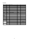
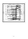
* About protections of each pin, see “Table 2 Correspondence of the connectors”.
Examples to be protected
- Connection between a port and +10[V] signal
- Short-circuiting between a port and ECL (-5.5[V]) output
signal
- Short-circuiting between output ports or between an
output port and the power supply
Examples NOT to be protected
- Applying +9[V] to the power supply
- Connection between a port and +24[V] signal