


(3/9)
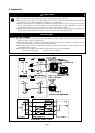
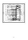
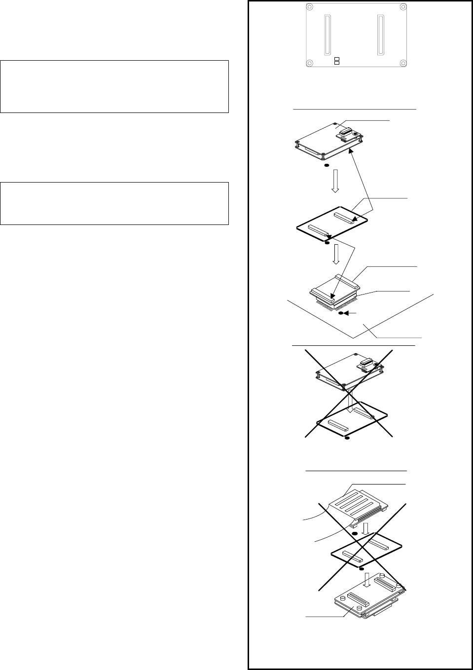
4. Connection Procedure (See Figure 2)
The procedure for connecting this product is shown below.
(1) Check that neither the RVC12 nor RVS12 on this product
has been disconnected using a tester.
- When the RVC12 and RVS12 are disconnected, this
product may have been damaged because of overload. Do
not connect this product with the emulator or user system.
As the emulator may also have been damaged, make a
request for inspection of it.
(2) Mount this product on the converter board. Make sure NOT
to use this product without the user system.
Install the connectors as follows.
Converter board CN1 = J3 of this product
Converter board CN2 = J4 of this product
- Check to see if power is off.
- Do not attach this product between the PCA7501EPBA
board and the M3T-FLX160-EPB.
- Be sure not to attach the board in a wrong direction.
(3) Mount the emulator on this product.
Install the connectors as follows.
Emulator J3 = J1 of this product
Emulator J4 = J2 of this product
Before using this product, be sure to read "5. Precautions" on
the next page.
Emulator
CN2 side
(2)
1pin
(3)
Converter board
User system
This product
CN1 side
J3
J4
40b
40a
1a
1b
40a
1a
40b
1b
RVC12
RVS12
(1) Check neither RVC12 nor
RVS12 have been disconnected
before using this product.
Socket
J1Side
J2 Side
(J4)
(J3)
(J4)
(J3)
Match the direction
of the connectors
Match the direction
of the connectors
Do NOT use without the
user system.
-
PCA7501EPBA
M3T-FLX160-EPB
-
Do not attach this product
between
the PCA7501EPBA board
and the M3T-FLX160-EPB.
Figure 2 Connection procedure of the R0E330850ACBP0