


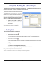


There are several versions of the timer function depending upon the peripherals available in the device. The default function is TimerADC
which we shall demonstrate here.
The timer function initialises an interrupt on an available internal timer. On a compare match in the timer module an interrupt is generated.
In the TimerADC code version the interrupt reads the last ADC conversion for the external potentiometer and uses the result to set the next
compare match value. The ADC conversion is then re-started.
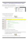
The interrupt initialisation is performed as part of the hardware setup. This is located in the file ‘interrupts.c’.
• Open the file ‘interrupts.c’ by double clicking on the file in the workspace view.
• Review this file and find the interrupt function that changes the LED pins, INT_MTU1_TGIA1(void)
• Set a breakpoint on the line where the LED pins are modified.
• Press ‘Go’ or ‘F5’ to run the code from the current
PC position.
The code will stop in the interrupt routine. It is now possible to step through the interrupt function.
• Remove the breakpoint in the interrupt by double clicking again before exiting the function.
• Press ‘Step Over’ to step over the instruction and observe the LEDs turn off.
• Press ‘Go’ to run the code from the current PC
position.
The code will now run to the infinite loop at the end of Main(). The user LEDs should now be flashing. If the RSK supports an ADC you can
modify the flashing rate by adjusting the potentiometer on the board.
• Press ‘Stop’ on the debug tool bar.
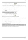
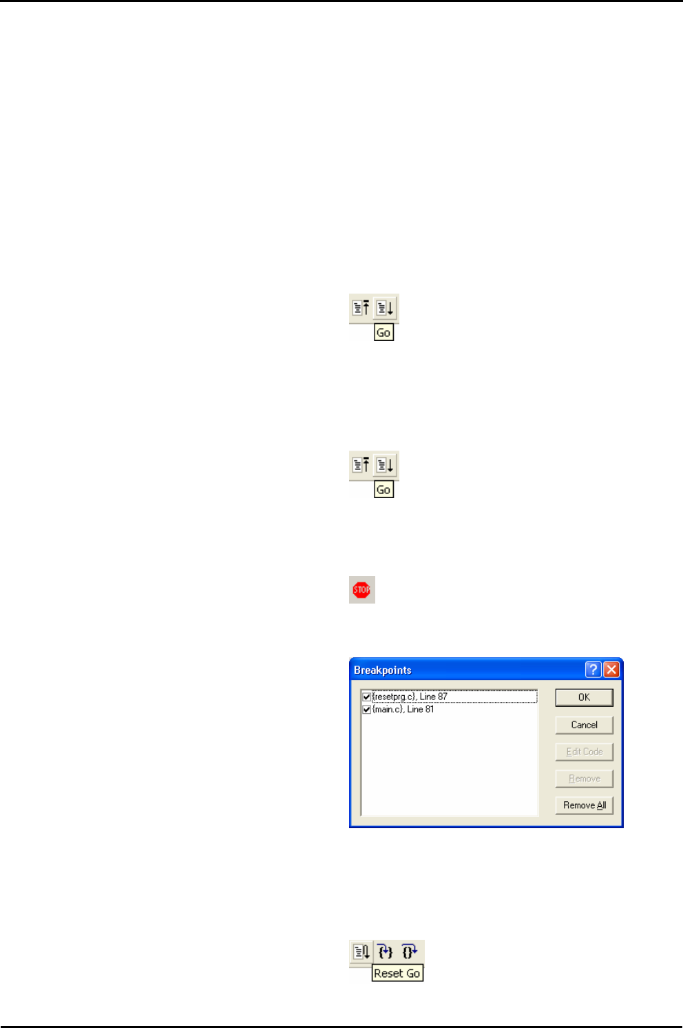
• Press ‘CTRL-B’ to open the breakpoint window.
• Select ‘Remove All’
• Press <OK>.
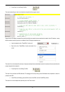
• Open the file ‘main.c’
• Insert a breakpoint on ‘StaticsTest();’.
The statics test is used to demonstrate that the initialisation has successfully copied all initialised variables from storage in flash to RAM.
• Press ‘Reset Go’ on the Debug Tool Bar.
The code will stop at the breakpoint. (Press a button to bypass the flashing LED test.)
12