


Chapter 1: Setting up the Interface and Test Board
10 RIM OEM Radio Modem for GSM/GPRS Wireless Networks
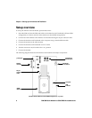
Connecting the radio modem
The 22-pin flat interface cable supplies clean, regulated power to the radio and carries most of the
data and all of the voice between the Interface and Test Board and the radio modem. This cable also
carries control and status signals, such as
ONI
.
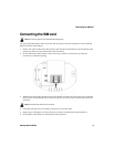
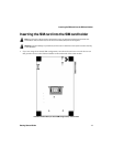
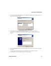
1. At the top of the radio modem, push the two black tabs up and away from the connector.
Connecting the 22-pin cable to the radio modem
2. With the blue side facing the Interface and Test Board, insert the end of the 22-pin cable into the
connector. Verify that the side with the bare pins is in direct contact with the pin side of the
connector.
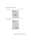
3. At the top of the radio modem, push the black tabs down toward the connector to secure the
cable.
4. Repeat steps 1 through 3 for the 22-pin connector on the Interface and Test Board.
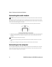
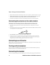
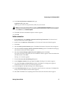
Connecting to the computer
Use the straight-through DB-9 serial cable to connect the Interface and Test Board to the computer.
Connect the male end of the cable to the Interface and Test Board. Connect the female end of the
cable to an available COM port on the computer.
Note: This step is only necessary if the radio modem is not already connected to the Interface and Test Board.
Note: Do not force the cable into the connector.