


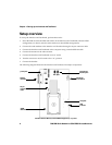
Connecting the SIM card
Getting Started Guide 9
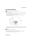
Connecting the SIM card
The 6-pin flat SIM interface cable carries the data and power between the Interface and Test Board
SIM slot and the radio modem.
1. Remove the radio modem from the Interface and Test Board: unfasten the nuts and lift the radio
modem up and away from the Interface and Test Board.
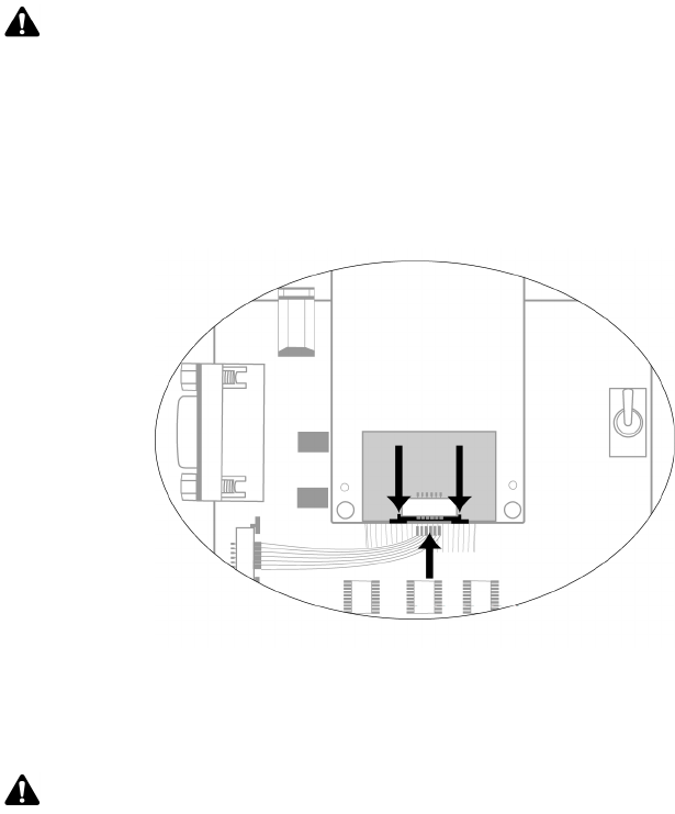
2. On the underside of the modem, on the connector, push the two black tabs up from the
connector to widen the opening.
Underside of radio modem showing the 6-pin connector
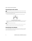
3. With the blue side facing the Interface and Test Board, insert the end of the cable 6-pin cable into
the connector. Verify that the side with the bare pins is in direct contact with the pin side of the
connector.
4. Push the black tabs down toward the connector to secure the cable.
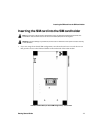
5. Repeat steps 2 through 4 to connect the 6-pin connector to the Interface and Test Board.
6. Re-attach the radio modem to the Interface and Test Board.
Note: This task only applies to the off-board SIM configuration.
Note: Do not force the cable into the connector.