


Chapter 1: Setting up the Interface and Test Board
8 RIM OEM Radio Modem for GSM/GPRS Wireless Networks
Setup overview
To set up the Interface and Test Board, perform these tasks:
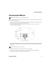
1. Insert the SIM card into the SIM card holder on the Interface and Test Board (off-board SIM
configuration) or directly onto the radio modem (on-board SIM configuration).
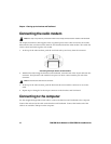
2. Connect the radio modem to the Interface and Test Board using the 22-pin connector cable.
3. Connect the Interface and Test Board to the computer using a standard RS-232 cable.
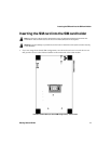
4. Connect the antenna to the radio modem.
5. Connect the Interface and Test Board to an AC outlet.
6. Turn the transceiver on/off switch to the “on” position
7. Connect the headset.
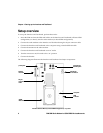
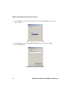
The following diagram illustrates the Interface and Test Board and major components.
Interface and Test Board (on-board SIM configuration) – top view
microphone/
transceiver
test point
LED
power jack
RS-232
22-pin
GPRS
speaker jacks
interface
indicator
connector
Radio Modem
cable
Mic Spkr
on/off switch