


6
Panel descriptions
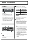
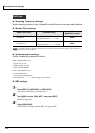
Front Panel
ADAT indicator
This indicator will light green if an ADAT
interface signal is being input to the ADAT
digital IN connector.
POWER indicator
When the R-BUS device connected to the R-BUS
connector is powered up, this indicator will light
red to indicate that power is being supplied to
the DIF-AT24.
* Power is supplied to the DIF-AT24 via the R-BUS
connector.
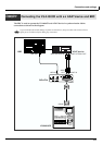
MIDI IN/OUT connectors
These are used mainly for MTC synchronization.
The data that is transmitted from the MIDI OUT connector
will depend on the settings of the R-BUS device connected to
the R-BUS connector.
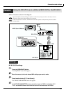
Rear Panel
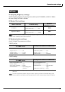
MASTER CLK (Master clock) switch
This switches the master clock (sampling clock)
synchronization.
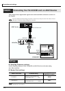
ADAT OUT/IN (ADAT digital out/in)
connector
This is the ADAT digital interface.
It allows eight channels of digital audio data to
be transferred between the DIF-AT24 and an
ADAT-compatible digital device.
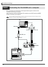
R-BUS connector
Provides for the input/output of eight channels
of digital audio data, thus allowing the exchange
of data between the DIF-AT24 and an R-BUS
device to take place. Also transmits/receives
synchronization signals.
* Power is supplied to the DIF-AT24 via the R-BUS
connector.
• Connect only an R-BUS device to the R-BUS connector.
You must never connect a device with a SCSI, RS-232C,
or parallel interface. Even though the connectors on such
devices may look similar, they are incompatible, and
damage and/or malfunction could result if you attempt
their connection. Also, you must use only a special R-BUS
cable to make connections.
• You must turn off the power of the R-BUS device before
connecting or disconnecting the R-BUS cable. If you
connect or disconnect the cable while power is being
supplied, the external R-BUS device will stop working
correctly, and the DIF-AT24 or the external R-BUS device
may also be damaged.
• The specifications for “R-BUS” are identical to those of
RMDB2 and RMDB II. You can use it with any device
that is marked “RMDB2” or “RMDB II.”
• R-BUS (RMDB2) is not compatible with the older RMDB
specification.
MASTER CLK
switch
Master clock device
Set to [R-BUS]
When using the R-BUS device
connected to the R-BUS
connector as the master clock.
Set to [ADAT]
When using the digital device
connected to the ADAT OUT/IN
connector as the master clock