


Vista KVM-Series Installation and Operations Manual
29
Appendix D. Rack mount instructions
The optional rack mount kit includes the following items:
§ Two black anodized mounting brackets.
§ Four 6 - 32 x 3/8” flat head mounting screws.
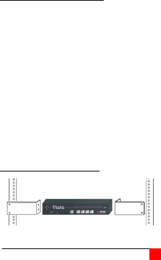
To rack mount your Vista switch, attach the two rack mounting brackets to
your unit with the short flange against the unit using the four screws
provided. Using hardware other than that provided could cause damage
to the electronics and/or result in loss of mounting integrity. Do not over
tighten the screws used to mount the unit to the mounting brackets.
Secure the mounting brackets to the rack using the appropriate size bolts,
nuts and lock washers.
The following general guidelines should be observed when installing your
unit into a rack.
1. The Vista switch is designed to work in an ambient temperature of 0
ο
C
to 55
ο
C (32
ο
F – 131
ο
F).
2. Do not block power supply vents or otherwise restrict airflow when
rack-mounting this unit.
3. Mechanical loading of the rack should be considered to prevent
instability.
4. Tighten all connectors securely and provide adequate strain relief for
all cables.
5. Provide a grounded power source to all units. Pay special attention to
overall branch circuit load ratings before connecting equipment to this
source. Overloaded circuits are potential fire hazards and can cause
equipment failures or poor performance.
Appendix E. Rack mount illustration