


6
Placement
The RB-1070 generates heat as part of its nor-
mal operation. The heat sinks and ventilation
openings in the amplifier are designed to
dissipate this heat. The ventilation slots in the
top cover must be open. There should be 10
cm (4 inches) of clearance around the chas-
sis, and reasonable airflow through the in-
stallation location, to prevent the amplifier from
overheating.
Likewise, remember the weight of the ampli-
fier when you select an installation location.
Make sure that the shelf or cabinet can sup-
port its considerable bulk. Again, use com-
mon sense.
AC Power and Control
AC Power Input
Because of its high power rating, the RB-1070
can draw considerable current. Therefore, it
should be plugged directly into a 2-pin po-
larized wall outlet. Do not use an extension
cord. A heavy duty multi-tap power outlet strip
may be used if it (and the wall outlet) is rated
to handle the current demanded by the
RB-1070 and all the other components con-
nected to it.
Be sure the power switch on the front panel
of the RB-1070 is turned off (in the out posi-
tion). Then, connect the supplied power cord
to the AC power outlet.
Your RB-1070 is configured at the factory for
the proper AC line voltage in the country where
you purchased it (either 115 volts AC or 230
volts AC with a line frequency of either 50
Hz or 60 Hz). The AC line configuration is
noted on a decal on the back panel.
Note:
Should you move your RB-1070
amplifier to another country, it is possible
to reconfigure your amplifier for use on a
different line voltage. Do not attempt to
perform this conversion yourself. Opening
the enclosure of the RB-1070 exposes you
to dangerous voltages. Consult a qualified
service person or the Rotel factory service
department for information.
If you are going to be away from home for
an extended period of time such as a month-
long vacation, it is a sensible precaution to
unplug your amplifier (as well as other au-
dio and video components) while you are
away.
Power Switch and Power
Indicator
The power switch is located on the front panel
of your amplifier. To turn the amplifier on, push
the switch in. The LED indicator above the
switch will light, indicating that the amplifier
is turned on. To turn the amplifier off, push
the button again and return it to the out po-
sition.
Trigger ON/OFF
Mode Selector
The Amplifier provides the option for manual
or automatic power on/off operation. These
modes are selectable using a toggle switch
on the back panel.
With the switch in the +12V TRIGGER ON
position, the amplifier is turned on automati-
cally when a 12V trigger signal is present at
the 3.5 mm Jack of TRIGGER IN on the rear
panel. The amplifier will go into standby mode
if the +12V signal is not present. The front panel
POWER SWITCH overrides this function. It must
be ON for the +12V trigger to work. Turning
the switch OFF cuts power to the amplifier,
regardless of whether or not a trigger signal
is present.
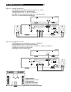
12V Trigger Input
and Output
The jack labeled IN is for connecting the
3.5mm Plug/Cable carrying a +12 volt trig-
ger signal to turn the amplifier on and off.
To use this feature the toggle switch must be
set to the ON position. This input accepts any
control signal (AC or DC) ranging from 3 volts
to 30 volts.
The jack labeled OUT is for connecting an-
other 3.5mm plug/cable to provide a 12V
trigger signal to other components. The 12V
output signal is available whenever a +12 volt
trigger signal is applied to the IN connector.
Protection Circuitry
The RB-1070 features a thermal protection cir-
cuit that protects the amplifier against potential
damage in the event of extreme or faulty
operating conditions. Unlike many designs,
the RB-1070’s protection circuit is indepen-
dent of the audio signal and has no impact
on sonic performance. Instead, the protection
circuit monitors the temperature of the output
devices and shuts down the amplifier if tem-
peratures exceed safe limits.
Most likely, you will never see this protection
circuitry in action. However, should a faulty
condition arise, the amplifier will stop play-
ing and the LED indicator on the front panel
will light up.
If this happens, turn the amplifier off, let it cool
down for several minutes, and attempt to iden-
tify and correct the problem that caused the
protection circuitry to engage. When you turn
the amplifier back on, the protection circuit
will automatically reset and the indicator LED
should go out.
In most cases, the protection circuitry activates
because of a fault condition such as shorted
speaker wires, or inadequate ventilation lead-
ing to an overheating condition. In very rare
cases, highly reactive or extremely low im-
pedance speaker loads could cause the pro-
tection circuit to engage.
If the protection circuitry triggers repeatedly
and you are unable to isolate and correct the
faulty condition, contact your authorized Rotel
dealer for assistance in troubleshooting.
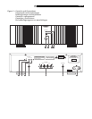
Input Signal Connection
[See Figure 2 for normal stereo wir-
ing illustration.]
The RB-1070 has conventional RCA type in-
put connectors, the type found on nearly all
audio equipment.
Note: To prevent loud noises that neither
you nor your speakers will appreciate,
make sure the amplifier is turned off when
you make any signal connections.
Select a high quality pair of audio intercon-
nect cables. Connect the left channel output of
your preamp to the left channel input on the
RB-1070. Connect the right channel output of
your preamp to the right channel input.
RB-1070 Stereo Power Amplifier