


13
© 2008 RuggedCom Inc. All rights reserved Rev106
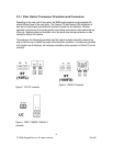
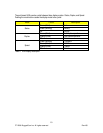
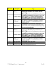
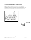
Terminal # Description Usage
1 PS1 Live / +
PS1 Live / + is connected to the positive (+) terminal if the
power source is DC or to the (Live) terminal if the power
source is AC.
2 PS1 Surge Ground
PS1 Surge Ground is connected to the Chassis Ground via
a jumper on the terminal block. Surge Ground is used as the
ground conductor for all surge and transient suppression
circuitry. NOTE: Surge Ground must be disconnected from
Chassis Ground during HIPOT (dielectric strength) testing.
3 PS1 Neutral / -
PS1 Neutral / - is connected to the negative (-) terminal if
the power source is DC or to the (Neutral) terminal if the
power source is AC.
4 Chassis Ground
Chassis Ground is connected to the Safety Ground
terminal for AC inputs or the equipment ground bus for DC
inputs. Chassis ground connects to both power supply surge
grounds via a removable jumper.
5 PS2 Live / +
PS2 Live / + is connected to the positive (+) terminal if the
power source is DC or to the (Live) terminal if the power
source is AC.
6 PS2 Surge Ground
PS2 Surge Ground is connected to the Chassis Ground via
a jumper on the terminal block. Surge Ground is used as the
ground conductor for all surge and transient suppression
circuitry. NOTE: Surge Ground must be disconnected from
Chassis Ground during HIPOT (dielectric strength) testing.
7 PS2 Neutral / -
PS2 Neutral / - is connected to the negative (-) terminal if
the power source is DC or to the (Neutral) terminal if the
power source is AC.
8 Relay NO Contact Normally open, failsafe relay contact.
9 Relay Common Failsafe relay common contact.
10 Relay NC Contact Normally closed, failsafe relay contact.
Table 3: M2100 Power terminal block connection description