


20
© 2008 RuggedCom Inc. All rights reserved Rev106
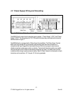
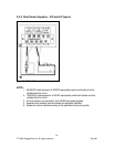
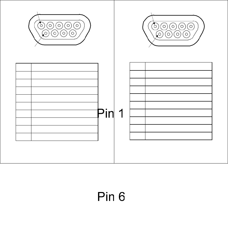
4.6 Twisted-Pair Data Ports
4.6.1 Micro-D Twisted-Pair Data Ports
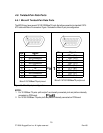
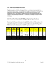
The M2100 may have several 10/100/1000BaseTX ports that allow connection to standard CAT-5
UTP cable with Micro-D connectors. Figure 15 shows the Micro-D port pin configuration.
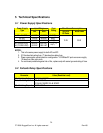
Pin Signal
1TX+
2 No Connection
3 No Connection
4 No Connection
5RX+
6TX-
7 No Connection
8 No Connection
9RX-
Micro-D 10/100BaseTX port pin-out
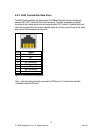
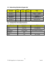
Pin Signal
1TP1+ (B+)
2 TP3+ (D+)
3 No Connection
4 TP2+ (C+)
5TP0+ (A+)
6 TP1- (B-)
7 TP3- (D-)
8 TP2- (C-)
9 TP0- (A-)
Micro-D 10/100/1000BaseTX port pin-out
Figure 15: Micro-D port pin configuration
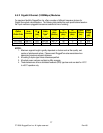
NOTES:
1. For 10/100Base-TX ports: pin2 and pin7 are internally connected, pin4 and pin8 are internally
connected on PCB board.
2. For 10/100/1000Base-TX ports: pin3 and pin8 are internally connected on PCB board.