


13
2008 RuggedCom Inc. All rights reserved Rev104
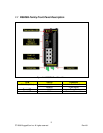
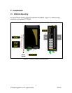
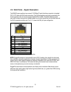
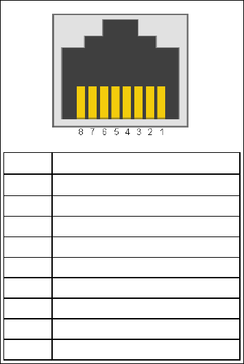
2.6 RJ45 Ports – Signal Description
The RS900G series switches have several 10/100BaseTX ports that allow connection to standard
CAT-5 UTP cable with RJ45 male connectors. The RJ45 receptacles are directly connected to the
chassis ground on the unit and can accept shielded CAT-5 cables. If shielded cables are used,
care must be taken to ensure the shielded cables do not form a ground loop via the shield wire and
the RJ45 receptacles at either end. Fig. 2.6.1 shows the RJ45 port pins configuration.
Pin Signal
1 +Rx
2 -Rx
3 +Tx
4 No Connection
5 No Connection
6 -Tx
7 No Connection
8 No Connection
Case Shield (Chassis Ground)
Fig. 2.6.1 shows the RJ45 port pins configuration.
NOTE: RuggedCom does not recommend the use of CAT-5 cabling of any length for critical real-
time substation automation applications. However, transient suppression circuitry is present on all
copper ports to protect against damage from electrical transients and to ensure IEC 61850-3 and
IEEE 1613 Class 1 conformance. This means that during the transient event communications
errors or interruptions may occur but recovery is automatic.
RuggedCom also does not recommended to use these ports to interface to field devices across
distances which could produce high levels of ground potential rise, (i.e. greater than 2500V) during
line to ground fault conditions.