


8
2008 RuggedCom Inc. All rights reserved Rev104
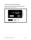
2.2 Power Supply Wiring and Grounding
2.2.1 HI Power Supply Wiring and Grounding
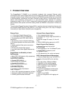
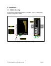
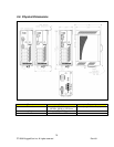
Figure 2.2.1 RS900G Family Power Supply Inputs
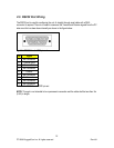
The RS900G family HI power supply inputs are identical and are connected as follows:
1. +/L should be connected to AC (Hot)
2. -/N should be connected to AC (Neutral)
3. Surge Ground is connected to the Chassis Ground via a braided cable or other
appropriate grounding wire. Surge Ground is used as the ground conductor for all surge
and transient suppression circuitry internal to the RS900G unit.
4. Chassis Ground should be connected to the AC Ground terminal
Notes:
1. Equipment must be installed according to the applicable country wiring codes.
2. Surge Ground MUST be disconnected from the Chassis Ground during HIPOT (dielectric
strength) testing.
3. All line-to-ground transient energy is shunted to the Surge Ground terminal. In cases
where users require the inputs to be isolated from ground, remove the ground braid
between Surge and Chassis Ground. Note that all line-to-ground transient protection
circuitry will be disabled.