


2. Installation
RuggedCom® RuggedSwitch™ 15 RS900GP Installation Guide Rev 100
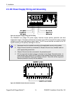
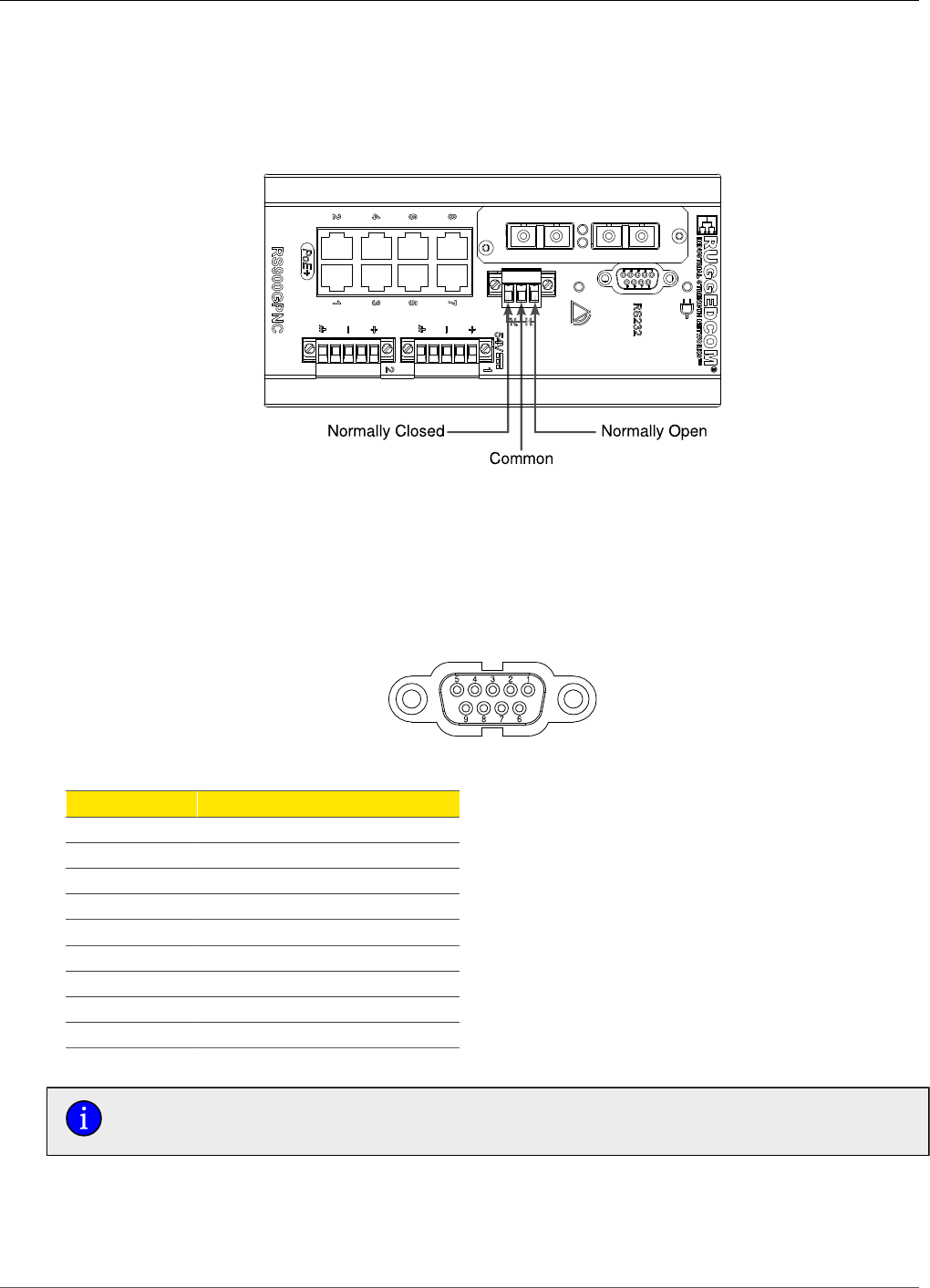
2.4. Failsafe Output Wiring and Specifications
The “Failsafe” output relay is provided to signal critical error conditions that may occur on the
RS900GP. The contacts are energized upon power up of the unit and remain energized until an
alarm condition or power loss occurs.
Figure 2.7. Failsafe Output Relay
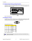
2.5. RS232 Port Wiring
The RS232 port is used for configuring the unit. A straight-through serial cable with a DB-9
connector is required. There is no need to crossover the Transmit and Receive signals from the
PC side since this has been done internally as shown in the figure below.
Figure 2.8. RS232 Female Connector
Pin Signal
1 No Connection
2 Transmit Data
3 Receive Data
4 No Connection
5 Ground
6 No Connection
7 No Connection
8 No Connection
9 No Connection
Table 2.1. RS232 Female DCE Pinout
This port is not intended to be a permanent connection and the cable shall be less
than 2m (6.5 ft) in length.