


Samsung Electronics
Service Manual
Circuit Description
12-4
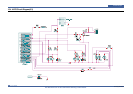
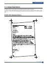
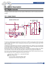
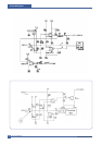
12.1.3 Motor Driver
A motor drive circuit is decided when selecting a driver IC. (Supplied by vendor) ML1610 uses the motor driver IC of
AN44060. However, the sensing resistance Rs value and the Vreference resistance value are variable according to
the motor drive current value.
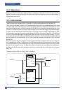
12.1.4 LSU Controller
The laser scanning unit controller (LSUC) of Jupiter4E is a block for interface between PVC block and LSU.
LSUC sends the video data received from PVC and the laser diode turn On/Off signal created by inner 21 bit counter
to the laser diode of LSU. LSU creates the horizontal sync signal (nHSYNC) by sensing the inputted diode turn on/off
signal with the attached sensor. nHSYNC is inputted to PVC and LSUC as a signal that informs the beginning of one
line. Also, LSU makes the activity of nLREADY signal (ready to print) low when the polygon motor becomes regular-
ly rotating. LSU can recognize the regular rotation status of the polygon motor by reading nLREADYFlag bit in SFR.
Once the polygon motor regularly rotates, it sends the page sync signal (nPSync) to PVC by writing ‘1’ at LSUCON[5]
in LSUC, and PVC starts operating for one page printing. After that, every time nHSYNC signal is created, PVC sens-
es the signal and outputs the video data (PVC_VDO) to LSUC. At this time, LSUC creates the video window (Printing
area) and masks it on the video data sent by PVC. LSUC sends the completed video data (LSU_VDO) to the laser
diode in LSU.
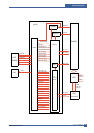
Also, LSUC supplies LSU_CLK, created by counting the system clock with the operation clock source of LSU, for the
use of substitution for oscillator. The SFR is set up in IsuSfr block by receiving the bus control signal from APB bus,
and the settled register values are redelivered to IsuCon block. IsuCon block creates a signal for controlling the laser
diode of LSU and outputs it to a pad. The digital filter module is a digital filter to provide against the noise loaded in
nHSYNC and nLREADY signal which directly get into the chip. It is three layer filter, and the delay time is 3*System
Clock Time.
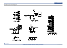
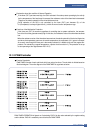
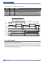
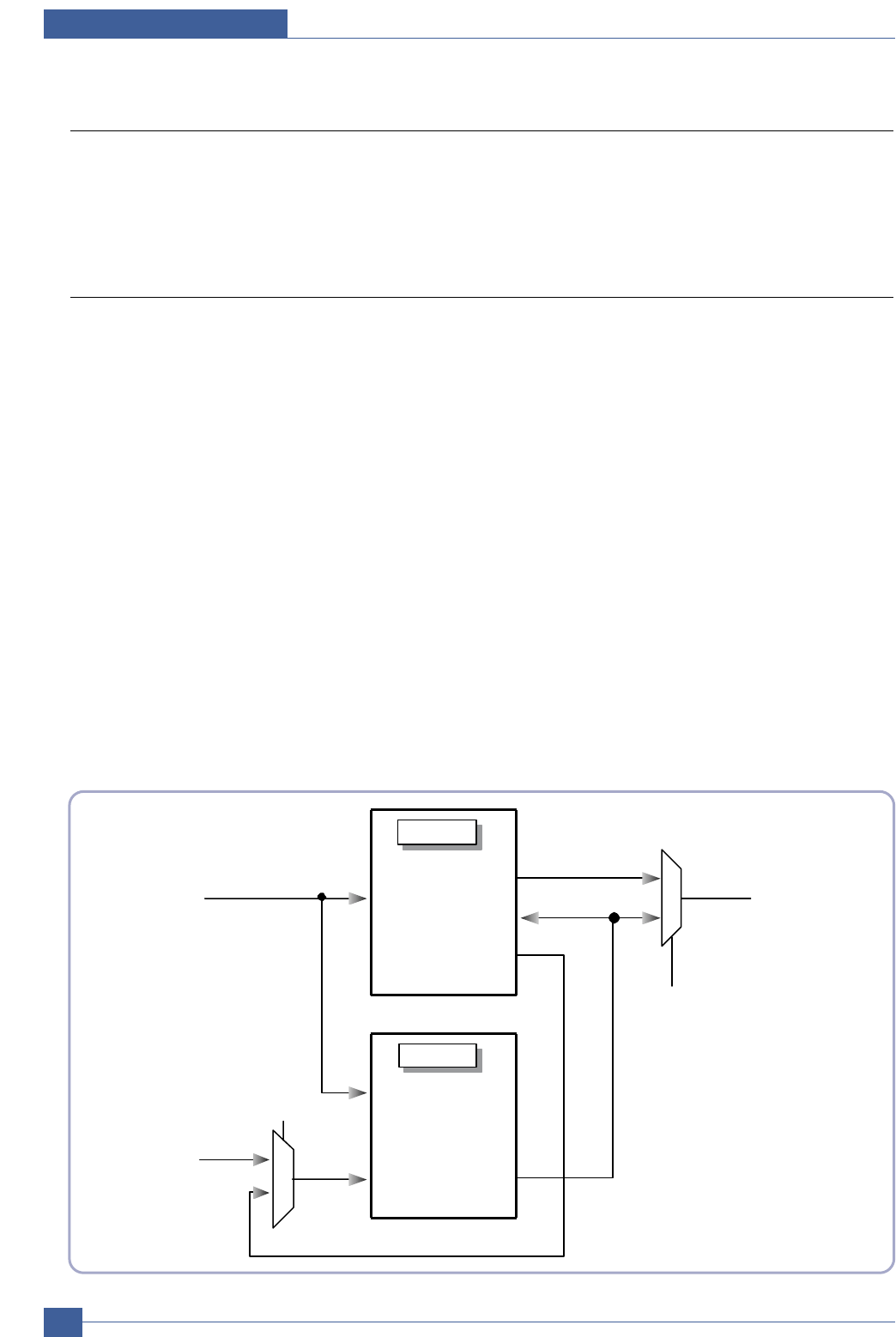
The interface between PVC and LSUC is shown in the picture.
LSUC
nHSYNC
nHSYNC
LSU_VDO
PVC_VDO
nPSync
nFSYNC
nFSYNC
nLSYNC
VDO
PVC
PVC_TEST_EN
PVC_TEST_EN
1
0
0
1
LSU_VDO