


Unit 4: Printer Configuration
S8400 Series Operator Manual
4-24 PN: 9001160B
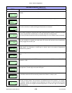
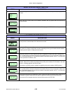
Allows the printer to be switched to operate in the thermal transfer or direct thermal mode as
desired.
Allows the pitch sensor mode to be selected relative to the media type being used.
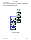
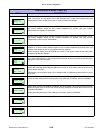
This feature determines the intensity of the print head elements when enabled. The printer will go
into error mode when a malfunctioning print head element is detected.
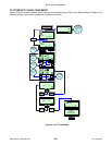
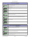
This screen will appear if the print head check feature has been enabled. Choose for the head
check to be performed unconditionally or only when barcodes are being printed.
Previously printed barcodes should be scanned following an error to determine their functionality.
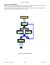
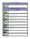
Set this feature to enable or disable an external signal for other printer’s communication port. If
the port is enabled, an external print start signal can be sent and received using an appropriate
device plugged into the EXT port.
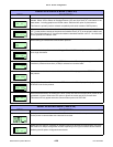
Appears only if the printer’s external signal feature has been enabled to allow selection of the
output signal. For information on which type to choose, refer to the printer’s Programming
Reference for guidance.
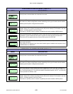
Allows configuration as to whether the reprint function may be activated via the external signal
port.
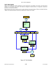
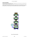
Allows for selection of specific SEMBL program to be stated when SEMBL mode AUTO START
selection is YES.
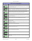
This menu allows for the printer to be configured to print zeros with or without a diagonal slash
through them. This will apply to all printer font types.
The printer can be set to go into the online mode when powered on. Otherwise, the printer starts
in the offline state and must be manually placed online before it is ready to print.
Print offset refers to the vertical and horizontal shifting of the entire print area relative to the label
and the print start position. The movement is incremental by dots in the positive (+) or negative
(-) direction. Positive and negative vertical adjustment is toward or away from the print head
respectively. Positive and negative horizontal adjustment is to the left or right of the reference
point respectively.
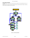
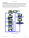
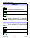
ADVANCED MODE (TABLE 4-2)
MENU DESCRIPTION
PRINT METHOD
TRANSFER DIRECT
SENSOR TYPE
GAP
TOP I-MARK
BOTTOM I-MARK
HEAD CHECK
ENABLE DISABLE
HEAD CHECK
NORMAL BARCODE
EXTERNAL SIGNAL
ENABLE DISABLE
EXTERNAL SIGNAL
TYPE 1 TYPE 2
TYPE 3 TYPE 4
EXTERNAL REPRINT
ENABLE DISABLE
START PROGRAM
NONE
ZERO SLASH
YES NO
AUTO ONLINE
YES NO
PRINT OFFSET
V: +XXXX H: +XXXX