


Network Management Card & Modbus/Jbus 34022321XT indice :AE Page 4/98
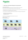
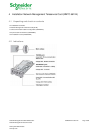
Network Management Teleservice Card
APC by Schneider Electric
www.apc.com
10
MODBUS/JBUS INSTALLATION & USE ................................................................................................................................................ 65
10.1
I
NSTALLATION
....................................................................................................................................................................................... 65
10.1.1
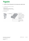
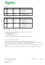
RS232 link configuration and connection..................................................................................................................................... 65
10.1.2
RS485 link configuration and connection..................................................................................................................................... 66
10.1.2.1
RS485 connection.............................................................................................................................................................. 66
10.1.2.2
RS485 link configuration for 2 wires connexion .................................................................................................................. 68
10.1.2.3
RS485 link configuration for 4 wires connexion .................................................................................................................. 70
10.1.3
Configuration of the JBUS/MODBUS communication parameters............................................................................................... 72
10.1.3.1
Choice 1: Display Jbus settings.......................................................................................................................................... 73
10.1.3.2
Choice 2: Modify Jbus settings........................................................................................................................................... 73
10.1.3.3
Choice 3: Display Jbus diagnostics .................................................................................................................................... 73
10.1.3.4
Choice 4: Reset Jbus diagnostics....................................................................................................................................... 73
10.1.3.5
Choice 5: Return to Jbus Default Configuration.................................................................................................................. 74
10.1.3.6
Choice 6: Display Jbus frames ........................................................................................................................................... 74
10.2
A
DDITIONAL
W
EB PAGES
....................................................................................................................................................................... 75
10.3
M
ODBUS REGISTER MAP
........................................................................................................................................................................ 76
10.3.1
Detailled status table................................................................................................................................................................... 76
10.3.2
Measurement table ..................................................................................................................................................................... 78
10.3.3
Environnement Sensor Table...................................................................................................................................................... 79
10.3.3.1
Sensor Status table............................................................................................................................................................ 79
10.3.3.2
Sensor Measurements table............................................................................................................................................... 79
10.3.3.3
Sensor customisation table (RO)........................................................................................................................................ 80
10.3.4
Examples of Modbus register map.............................................................................................................................................. 81
10.3.4.1
Global overview.................................................................................................................................................................. 81
10.3.4.2
UPS on AC Normal input.................................................................................................................................................... 82
10.3.4.3
UPS on Battery .................................................................................................................................................................. 83
10.3.4.4
Low Battery Warning.......................................................................................................................................................... 84
10.3.4.5
UPS on Bypass due to End of battery runtime.................................................................................................................... 85
10.3.4.6
UPS on Bypass due to manual order.................................................................................................................................. 86
10.3.4.7
UPS on Manual Bypass...................................................................................................................................................... 87
10.3.4.8
UPS running Power Saving Mode ...................................................................................................................................... 88
10.3.4.9
Communication lost............................................................................................................................................................ 89
11
APPENDICES.......................................................................................................................................................................................... 90
11.1
T
ABLES OF ALARMS AND EVENTS
........................................................................................................................................................... 90
11.1.1
Table of alarms and UPS events................................................................................................................................................. 90
11.1.2
Table of system alarms............................................................................................................................................................... 92
11.2
SNMP
OBJECTS
.................................................................................................................................................................................... 93
11.2.1
MGE MIB .................................................................................................................................................................................... 93
11.2.2
Table des TRAPS : (1.3.6.1.4.1.705.1.11)................................................................................................................................... 96
12
GLOSSARY............................................................................................................................................................................................. 97