


• 7 •
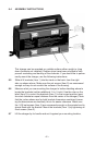
tighten the set screws (Item 4) to secure the brackets (Item 1), starting
with the top two brackets rst.
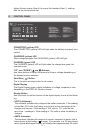
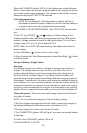
CONTROL PANEL9.
CONNECTED (yellow) LED
The CONNECTED (yellow) LED will light when the battery is properly con-
nected.
CHARGING (yellow) LED
When charging begins, the CHARGING (yellow) LED will light.
CHARGED (green) LED
The CHARGED (green) LED will light when the charger has gone into
maintain mode.
“UP” and “DOWN” ( and ) Buttons
Use these buttons to select the amount of time or voltage depending on
the display function selected.
Start/Stop ( ) Button
This is the start and stop button for all modes.
Digital Display
The Digital Display gives a digital indication of voltage, amperes or time,
depending on the DISPLAY function chosen.
Display Button
Use this button to set the function of the digital display to one of the follow-
ing:
VOLTS (Voltmeter)•
The voltmeter indicates the voltage at the battery terminals. If the reading
is less than 10.5-volts, the battery may be bad or the connection at the
charger may be poor. If the reading is 10.5 volts to 12.7 volts the bat-
tery is low – recharge it. If the reading is 12.8 volts or more the battery is
charged.
AMPS (Ammeter)•
The Ammeter indicates the amount of current, measured in amps, that is
being drawn by the battery ( 2 amps). For example, in a 20 amp charge
rate a typical discharged battery will initially draw approximately 20 amps.