


734348 Rev C 33
Introduction
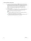
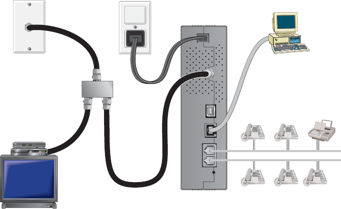
Installation Diagram
The following diagram illustrates one of the various connection options that are
available to you.
USBCABLE
POWER
ETHERNET 1/2
TELEPHONE REBOOT
EMTA
2
Power
Cord
Cable-Ready TV,
VCR, or Set-Top
Converter
PC
Ethernet
Cable
RF
Cable
RF
Cables
Cable
Splitter
T11717
BYPASS
VOLñ VOL+
CH+
CHñ
MENUGUIDEINFOA/B
POWER
Home Telephone Wiring
Line 1
Home Telephone Wiring
Line 2
To install the cable modem for telephone service
1 Connect a telephone, fax machine, or analog modem to each of the appropriate
RJ-11 ports on the cable modem.
Notes:
The cable modem provides one line of telephone service on each of the RJ-11
connectors.
Service must be set up and enabled by the telephone service provider.
The two center conductors (pins 3 and 4) on the RJ-11 connector provide
electrical connections to directly attached telephone devices or to a
permanently installed in-home telephone wiring network.
The telephone port labeled Line 1 also supports multi-line telephone devices.
Line 1 is supported on pins 3 and 4, and Line 2 is supported on pins 2 and 5.
The use of telephones that require electrical connections to other RJ-11 pins
requires an adapter.
2 After all telephone connections are complete, insert the AC power cord into the
power connector on the back of the cable modem, and then plug the cord into an
AC power source.