


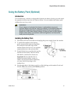


48 4004041 Rev C
Front Panel LED Status Indicator Functions
Normal Operations
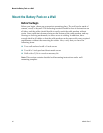
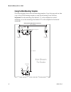
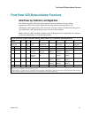
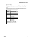
The following chart illustrates the appearance of the front panel LED status
indicators on the cable modem during normal operations.
Front Panel LED Status Indicators During Normal Operations
Front Panel
Indicator
Normal Operations
4
1
Line 2 On when line 2 is in use
5 Line 1 On when line 1 is in use
6 PC
On – When a single device is connected to either the Ethernet or USB port and no
data is being sent to or from the modem
Blinks – When only one Ethernet or USB device is connected and data is being
transferred between the consumer premise equipment (CPE) and the cable
modem
Off – When no devices are connected to either the Ethernet or USB ports
Note: With both Ethernet and USB devices connected to the modem at the same
time, when data is being transferred through only one of the devices (Ethernet or
USB), the light illuminates continuously. Whenever data is being sent through
both data ports (Ethernet and USB) simultaneously, the light blinks as described
above.
7 Cable On
8 Send Blinks – To indicate that the modem is sending data to the network
9 Receive Blinks – To indicate that the modem is receiving data from the network
10 Power On
1
Lights number 1, 2, and 3 (Replace Battery, Battery Low, and AC Power) are part of the optional
battery pack and are not affected by the operations of the modem.