


Front Panel LED Status Indicator Functions
45
Front Panel LED Status Indicator Functions
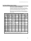
Initial Power Up, Calibration, and Registration
The following chart illustrates the sequence of steps and the corresponding
appearance of the cable modem front panel LED status indicators during power
up, calibration, and registration on the network. Use this chart to troubleshoot the
power up, calibration, and registration process of your cable modem.
Note: After the cable modem completes Step 7 (Registration Completed), the
modem proceeds immediately to Normal Operations. See Normal Operations,
next in this section.
Front Panel LED Status Indicators During Initial Power Up, Calibration, and Registration
Step → 1 2 3 4 5 6 7
Front Panel
Indicator
Self
Test
Downstream
Scan
Downstream
Signal Lock
Ranging Requesting
IP Address
Registering Registration
Completed
1
Power ON ON ON ON ON ON ON
2
Receive ON OFF OCCASIONAL
BLINKING
OCCASIONAL
BLINKING
OCCASIONAL
BLINKING
OCCASIONAL
BLINKING
ON
3
Send ON OFF OFF OCCASIONAL
BLINKING
OCCASIONAL
BLINKING
OCCASIONAL
BLINKING
ON
4
Cable ON SLOW
BLINKING
1 blink
MOMENTARY
ON
OFF BLINKING
2 blinks
BLINKING
4 blinks
ON
5
PC* ON ON
or
BLINKING
ON
or
BLINKING
ON
or
BLINKING
ON
or
BLINKING
ON
or
BLINKING
ON
6
Line 1 On Off Off Off Off Off Off
7
Line 2 On Off Off Off Off Off Off
8
Battery
Low
Off Off Off Off Off Off Off
9
Battery
Replace
Off Off Off Off Off Off Off
* The PC LED is on whenever a PC is connected to the modem, and it blinks to indicate that data is being transferred. If the
modem is used to provide telephone service only and is not connected to a PC, the PC LED is off.