


WebSTAR DPX2203C and EPX2203C VoIP Cable Modem User’s Guide
46
Normal Operations
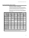
The following chart illustrates the appearance of the cable modem front panel
LED status indicators during normal operations.
Step → 8
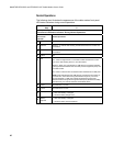
Front Panel LED Status Indicators During Normal Operations
Front Panel
Indicator
Normal Operations
1
Power ON
2
Receive BLINKS – To indicate data is being transferred between the modem and
the network
3
Send BLINKS – To indicate data is being transferred between the modem and
the network
4
Cable ON
5
PC
ON – When a single device is connected to either the Ethernet or USB
port and no data is being sent to or from the modem
BLINKS – When only one Ethernet or USB device is connected and data
is being transferred between the consumer premise equipment (CPE) and
the cable modem
OFF- When no devices are connected to either the Ethernet or USB ports
NOTE: With both Ethernet and USB devices connected to the modem at
the same time, when data is being transferred through only one of the
devices (Ethernet or USB), the indicator will illuminate continuously.
Whenever data is being sent through both data ports (Ethernet and USB)
simultaneously, the indicator will blink as described above.
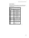
6
Line 1 ON when line 1 is in use
7
Line 2 ON when line 2 is in use
8
Battery Low
• OFF when battery is charged
• ON when battery charge is low
9
Battery
Replace
• OFF when battery is charged
• ON when battery must be replaced