


66 Constellation.2 SAS Product Manual, Rev. H
12.4.2 Physical characteristics
This section defines physical interface connector.
12.4.3 Connector requirements
Contact your preferred connector manufacturer for mating part information. Part numbers for SAS connectors
will be provided in a future revision of this publication when production parts are available from major connec-
tor manufacturers.
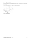
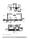
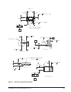
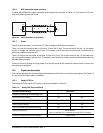
The SAS device connector is illustrated in Figures 14 and 15.
12.4.4 Electrical description
SAS drives use the device connector for:
• DC power
• SAS interface
• Activity LED
This connector is designed to either plug directly into a backpanel or accept cables.
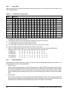
12.4.5 Pin descriptions
This section provides a pin-out of the SAS device and a description of the functions provided by the pins.
Table 13: SAS pin descriptions
Pin Signal name Signal type Pin Signal name Signal type
S1 Port A Ground P1* NC (reserved 3.3Volts)
S2* +Port A_in Diff. input pair P2* NC (reserved 3.3Volts)
S3* -Port A_in P3 NC (reserved 3.3Volts)
S4 Port A Ground P4 Ground
S5* -Port A_out Diff output pair P5 Ground
S6* +Port A_out P6 Ground
S7 Port A Ground P7 5 Volts charge
S8 Port B Ground P8* 5 Volts
S9* +Port B_in Diff. input pair P9* 5 Volts
S10* -Port B_in P10 Ground
S11 Port A Ground P11* Ready LED Open collector out
S12* -Port B_out Diff output pair P12 Ground
S13* +Port B_out P13 12 Volts charge
S14 Port B Ground P14* 12 Volts
P15* 12 Volts
* - Short pin to support hot plugging
NC - No connection in the drive.