


Constellation.2 SAS Product Manual, Rev. H 67
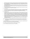
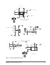
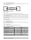
12.4.6 SAS transmitters and receivers
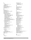
A typical SAS differential copper transmitter and receiver pair is shown in Figure 16. The receiver is AC cou-
pling to eliminate ground shift noise.
Figure 16. SAS transmitters and receivers
12.4.7 Power
The drive receives power (+5 volts and +12 volts) through the SAS device connector.
Three +12 volt pins provide power to the drive, 2 short and 1 long. The current return for the +12 volt power
supply is through the common ground pins. The supply current and return current must be distributed as
evenly as possible among the pins.
Three +5 volt pins provide power to the drive, 2 short and 1 long. The current return for the +5 volt power sup-
ply is through the common ground pins. The supply current and return current must be distributed as evenly as
possible among the pins.
Current to the drive through the long power pins may be limited by the system to reduce inrush current to the
drive during hot plugging.
12.5 Signal characteristics
This section describes the electrical signal characteristics of the drive’s input and output signals. See Table 13
for signal type and signal name information.
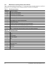
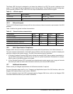
12.5.1 Ready LED Out
The Ready LED Out signal is driven by the drive as indicated in Table 14.
Table 14: Ready LED Out conditions
Normal command activity LED status
Ready LED Meaning bit mode page 19h
01
Spun down and no activity Off Off
Spun down and activity (command executing) On On
Spun up and no activity On Off
Spun up and activity (command executing) Off On
Spinning up or down Blinks steadily
(50% on and 50% off, 0.5 seconds on and off for 0.5 seconds)
Format in progress, each cylinder change Toggles on/off
l
TM
01
01
100100
T
XTX
T