


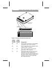
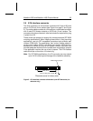

2.3 Remote LED configuration
The drive indicates activity to the host through the DASP– line (pin 39)
on the ATA interface. This line may be connected to a drive status
indicator driving an LED at 5V. The line has a 30 mA nominal current
limit; however, most external LEDs are sufficiently bright at 15 mA.
Because the LED drops 1.7 volts, we recommend that you place a
200-ohm resistor in series with the LED to limit the current to 15 mA.
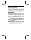
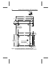
2.4 Drive mounting
You can mount the drive in any orientation using four screws in the four
side-mounting or four bottom-mounting holes. Allow a minimum clear-
ance of 0.030 inches (0.76 mm) for cooling around the entire perimeter
of the drive. The drive conforms to the industry-standard SFF-8200
mounting specifications and requires the use of SFF-8200-compatible
connectors in direct-mounting applications. See Figures 3 and 4 on
pages 20 and 21 for drive mounting dimensions.
Note
. Per SFF 8004 specifications, the I/O connector pins may extend
up to 0.015 inches beyond the edge of the head/disc assembly.
Caution
. This drive needs sufficient airflow so that the maximum surface
temperature at the center of the top cover of the drive does
not exceed 62°C (144°F).
Caution
. To avoid damaging the drive, use M3X0.5 metric mounting
screws only. Do not insert mounting screws more than
0.150 inches (3.81 mm) into the mounting holes. Do not over-
tighten the screws (maximum torque: 3 inch-lb).
Marathon 2250 and Marathon 1680 Product Manual 19