


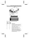
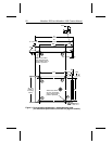
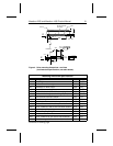
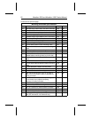
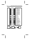
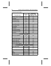

Mounting dimension specifications
Dim. Description inches mm
A16 Allowable range, side-to-side, pins within connector 0.003 0.08
A17 Pin top-to-bottom dimension 0.020 0.50
A18 + and – tolerance on pin top-to-bottom dimension 0.002 0.05
A19 Allowable range, top-to-bottom connector location 0.020 0.50
A20 Allowable range, top-to-bottom, pins in connector 0.003 0.08
A21 Connector pin length 0.152 3.86
A22 + and – tolerance on pin length 0.008 0.20
A23 Side mounting hole height 0.118 3.00
A24 Front-to-back location of side mounting holes 0.551 14.0
A25 Front-to-back distance between side mounting
holes
3.016 76.6
A26 Thread description, side mounting holes n/a M3
A27 Diam. of cylinder into which hole center must fall 0.020 0.50
A28 Distance between side of drive and center of
nearest bottom mounting holes (on pin-44 side)
0.160 4.06
A29 Side-to-side distance between bottom mounting
holes
2.430 61.72
A30 Front-to-back location of bottom mounting holes 0.551 14.0
A31 Front-to-back distance between bottom mounting
holes
3.016 76.6
A32 Thread description, bottom mounting holes n/a M3
A33 Diam. of cylinder into which hole center must fall 0.020 0.50
A34 Min. vertical clearance for mating connector 0.039 1.00
A35 Max. side-to-side distance from pin-44 edge of
HDA near I/O connector to start of clearance for
mating connector
0.315 8.00
A36 Min. side-to-side clearance from pin-44 edge of
I/O connector to any object interrupting
clearance of mating connector
2.370 60.20
A37 Diam. of datum targets and reference areas 0.315 8.00
A38 Min. thread depth, side mounting holes 0.118 3.00
A39 Min. pin centerline to chamfer above connector 0.049 1.25
A40 Min. chamfer above connector 0.010 0.25
A41 Min. thread depth, bottom mounting holes 0.098 2.50
S1 Maximum drive length to tips of I/O pins
(Non-SFF dimension—for reference only)
3.970 100.84
continued from previous page
22 Marathon 2250 and Marathon 1680 Product Manual