


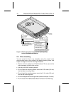
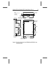

2.3 Drive mounting
You can mount the drive in any orientation using four screws in the
side-mounting holes or four screws in the bottom-mounting holes. See
Figure 3 on page 19 for drive mounting dimensions.
• Allow a minimum clearance of 0.030 inches (0.76 mm) around the
entire perimeter of the drive for cooling.
• Use only 6x32 UNC mounting screws.
• Do not insert the mounting screws more than 0.22 inches (5.6 mm)
into the bottom mounting holes.
• Do not insert the mounting screws more than 0.14 inches (3.6 mm)
into the side mounting holes.
• Do not overtighten the mounting screws (maximum torque: 3 inch-lb).
• Do not use a drive interface cable that is more than 18 inches long.
135
24
6
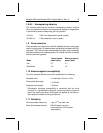
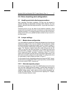
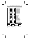
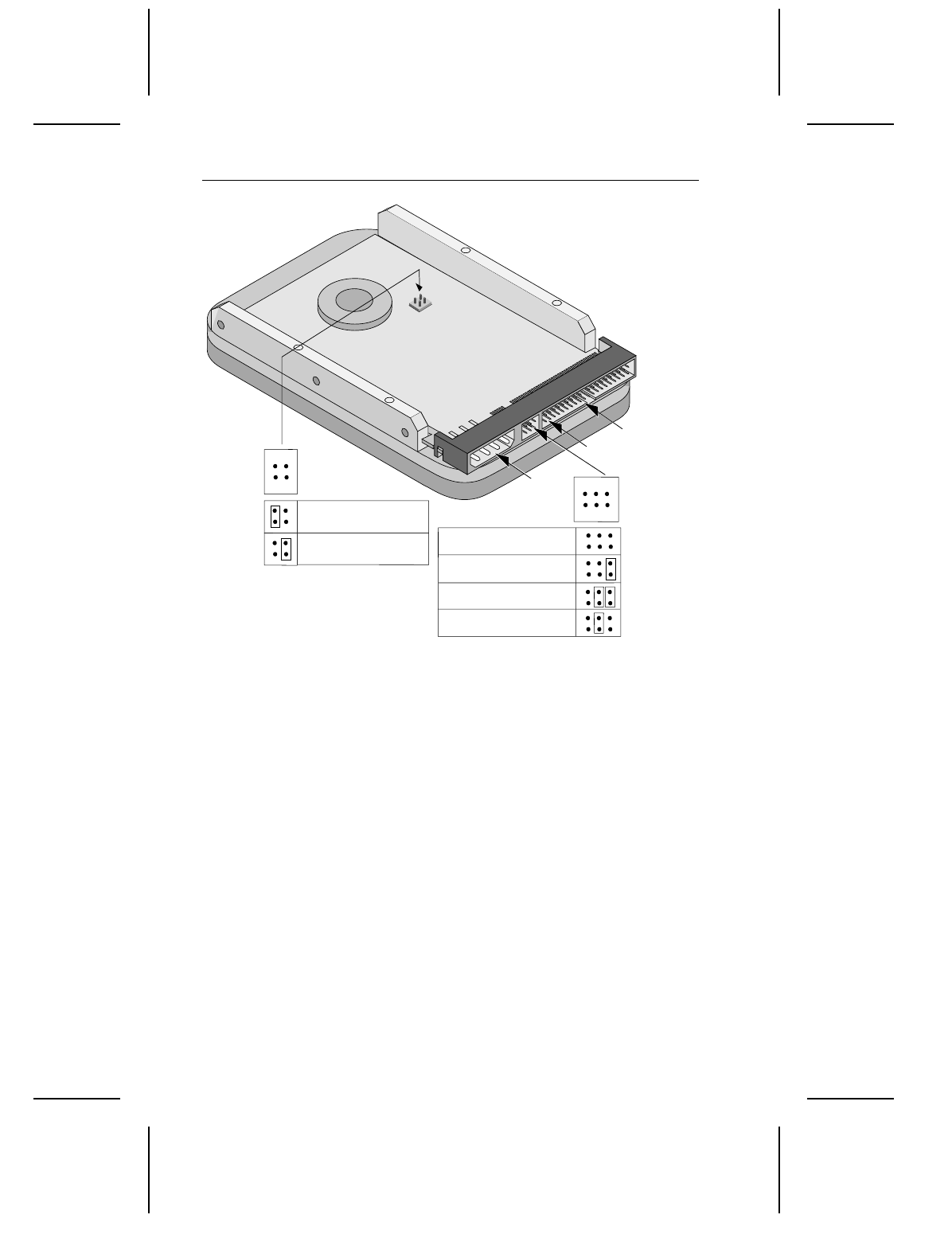
Master/slave
jumper settings
pin 1
4-pin power
connector
ATA interface
connector
42
31
Alternative
capacity
jumper
Full capacity (as shipped)
Limit capacity to 2.1 Gbytes
(4,092 cylinders)
1
Drive is slave
Drive is master in single-
or dual-drive system
Drive is master with
non-ATA-compatible slave
2
Enable cable select
3
Use this jumper setting if your
computer fails to boot because it
cannot address drives with more
than 4,096 cylinders.
1.
Use this jumper setting
only
if the drive does
not work with a single jumper on pins 5 and 6.
2.
Consult your computer manual to determine
if
y
our computer supports cable select
3.
1
2
3
4
Figure 2. Master/slave jumpers and alternate capacity jumper
for the ST33240A and ST32531A
18 Medalist 3240 and Medalist 2531 Product Manual, Rev. A